
Page 301 - Fluid mechanics, heat transfer, and mass transfer
P. 301
SHELL AND TUBE HEAT EXCHANGERS
282
. What are the normal margins of safety adopted while necessary to design the exchanger, taking into
specifying design pressures and temperatures for consideration such developments as mentioned
TEMA-specified exchangers? above.
& About 200 kPa greater than maximum expected dur- & Erosion problems should be controlled by control-
ing operation or at pump shutoff. ling flow velocities, especially in bends and other
& About 14 C greater than maximum temperature direction change areas, filtering the fluids from
while in service. debris and particulate matter and other measures.
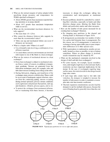
. What are the recommended maximum distances for . How are the number of tube passes increased for an
tube supports? existing heat exchanger? Illustrate.
& Not more than 1.0–1.25 m. & By changing pass partitions in the channel and
floating heads as illustrated in Figure 10.14.
. Why cannot the distances between tube supports be
more than the recommended values? & B arrangements accommodate less number of tubes
for a given shell diameter than A arrangements. For
& Tubes can sag and mechanical failure can occur if
this reason, use of B arrangements is restricted to
distances are increased.
exchangers having appreciable pass-to-pass temper-
. What is a duplex tube? Where is it used?
ature differences or to other special cases.
& It is a bimetallic tube involving a combination of two
& With vaporization or condensation, nozzles are nor-
different materials.
mally located as close as possible, to top or bottom
& It is used where corrosive environments are involved
centerlines. Where no phase change is involved,
with respect to one of the fluids in a heat exchanger.
nozzle orientations may be rotated by 90 .
. What are the sources of mechanical stresses in a heat
. What are the mechanical constraints involved in the
exchanger?
design of shell and tube heat exchangers?
& Every heat exchanger is subject to mechanical stres-
& For some reasons, for example, layout considera-
ses from a variety of sources, in addition to temper-
tions, tube lengths might have to be restricted. Such a
ature gradients. Stresses are generated from the
restriction can have important implications for the
fabrication techniques used, for example, tube and
design. In the case of exchangers requiring large
tube sheet stresses resulting from rolling in the tubes.
surface areas, the restriction drives the design toward
& During fabrication, shipping, and installation of the
large tube counts.
exchanger, many stresses could develop. These could & If such large tube counts lead to low tube side
be on account of inadequate support structure, stres-
velocities, the designer is tempted to increase the
ses from the connecting piping, stresses occurring
number of tube passes in order to maintain a reason-
during normal operation, process stream conditions
able tube side heat transfer coefficient.
such as pressures and pressure fluctuations, start-up,
& Thermal expansion considerations can also lead the
and shutdown, vibration, process upsets, and so on.
designer to opt for multiple tube passes, because the
& To protect the exchanger from permanent deforma-
cost of floating head is generally lower than the cost
tion or weakening from these stresses, it becomes
FIGURE 10.14 Typical pass partitions for two to eight tube passes.