
Page 296 - Fluid mechanics, heat transfer, and mass transfer
P. 296
HEAT EXCHANGERS 277
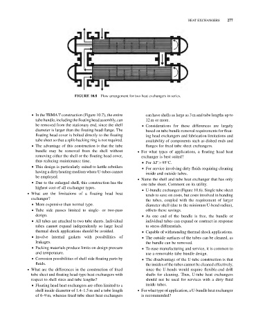
FIGURE 10.8 Flow arrangement for two heat exchangers in series.
& In the TEMAT construction (Figure 10.7), the entire can have shells as large as 3 m and tube lengths up to
tubebundle,includingthefloatingheadassembly,can 12 m or more.
be removed from the stationary end, since the shell & Considerations for these differences are largely
diameter is larger than the floating head flange. The based on tube bundle removal requirements for float-
floating head cover is bolted directly to the floating ing head exchangers and fabrication limitations and
tube sheet so that a split-backing ring is not required. availability of components such as dished ends and
& The advantage of this construction is that the tube flanges for fixed tube sheet exchangers.
bundle may be removed from the shell without . For what types of applications, a floating head heat
removing either the shell or the floating head cover, exchanger is best suited?
thus reducing maintenance time. & For DT > 95 C.
& This design is particularly suited to kettle reboilers
& For service involving dirty fluids requiring cleaning
having a dirty heating medium where U-tubes cannot
inside and outside tubes.
be employed.
. Name the shell and tube heat exchanger that has only
& Due to the enlarged shell, this construction has the
one tube sheet. Comment on its utility.
highest cost of all exchanger types.
& U-bundle exchanger (Figure 10.6). Single tube sheet
. What are the limitations of a floating head heat
tends to save on costs, but costs involved in bending
exchanger?
the tubes, coupled with the requirement of larger
& More expensive than normal type.
diameter shell (due to the minimum U-bend radius),
& Tube side passes limited to single- or two-pass offsets these savings.
design. & As one end of the bundle is free, the bundle or
& All tubes are attached to two tube sheets. Individual individual tubes can expand or contract in response
tubes cannot expand independently so large local to stress differentials.
thermal shock applications should be avoided. & Capable of withstanding thermal shock applications.
& Involve internal gaskets with possibilities of & The outside surfaces of the tubes can be cleaned, as
leakages. the bundle can be removed.
& Packing materials produce limits on design pressure & To ease manufacturing and service, it is common to
and temperature. use a removable tube bundle design.
& Corrosion possibilities of shell side floating parts by & The disadvantage of the U-tube construction is that
fluids. the insides of the tubes cannot be cleaned effectively,
. What are the differences in the construction of fixed since the U-bends would require flexible-end drill
tube sheet and floating head-type heat exchangers with shafts for cleaning. Thus, U-tube heat exchangers
respect to shell sizes and tube lengths? should not be used for services with a dirty fluid
& Floating head heat exchangers are often limited to a inside tubes.
shell inside diameter of 1.4–1.5 m and a tube length . For what type of application, a U-bundle heat exchanger
of 6–9 m, whereas fixed tube sheet heat exchangers is recommended?