
Page 294 - Fluid mechanics, heat transfer, and mass transfer
P. 294
HEAT EXCHANGERS 275
➢ K: Special cross-flow shell used as kettle reboiler, and hence heat transfer because of the smaller flow
with an enlarged shell to facilitate vapor area in the smaller exchangers that are required.
disengagement. . Compare arranging two shells in series and a two-pass
➢ X: Cross-flow shell. The shell side fluid enters at shell.
the top (or bottom) of the shell, flows across the & Two-pass shell is cheaper than two-shell arrange-
tubes, and exits from the opposite side of the shell. ment for the same duty.
The flow may be introduced through multiple & A two-pass shell has improved heat transfer
nozzles located strategically along the length of
efficiency.
the shell for better distribution. The pressure drop
. What are the features and plus and minus points of a
will be extremely low. Used for cooling and
fixed tube sheet heat exchanger?
condensing vapors at low pressures.
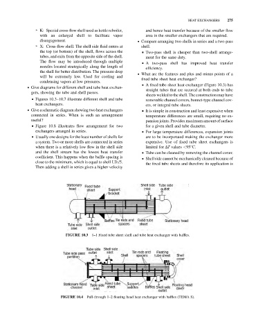
& A fixed tube sheet heat exchanger (Figure 10.3) has
. Give diagrams for different shell and tube heat exchan-
straight tubes that are secured at both ends to tube
gers, showing the tube and shell passes.
sheets welded to the shell. The construction may have
& Figures 10.3–10.7 illustrate different shell and tube
removable channel covers, bonnet-type channel cov-
heat exchangers. ers, or integral tube sheets.
. Give a schematic diagram showing two heat exchangers & It is simple in construction and least expensive when
connected in series. When is such an arrangement temperature differences are small, requiring no ex-
useful? pansion joints. Provides maximum amount of surface
& Figure 10.8 illustrates flow arrangement for two for a given shell and tube diameter.
exchangers arranged in series. & For large temperature differences, expansion joints
& Usually one designs for the least number of shells for are to be incorporated making the exchanger more
a system. Two or more shells are connected in series expensive. Use of fixed tube sheet exchangers is
when there is a relatively low flow in the shell side limited for DT values <95 C.
and the shell stream has the lowest heat transfer & Tube can be cleaned by removing the channel cover.
coefficient. This happens when the baffle spacing is
& Shell side cannot be mechanically cleaned because of
close to the minimum, which is equal to shell I.D./5.
the fixed tube sheets and therefore its application is
Then adding a shell in series gives a higher velocity
1–1 Fixed tube sheet shell and tube heat exchanger with baffles.
FIGURE 10.3
Pull-through 1–2 floating head heat exchanger with baffles (TEMA S).
FIGURE 10.4