
Page 293 - Fluid mechanics, heat transfer, and mass transfer
P. 293
SHELL AND TUBE HEAT EXCHANGERS
274
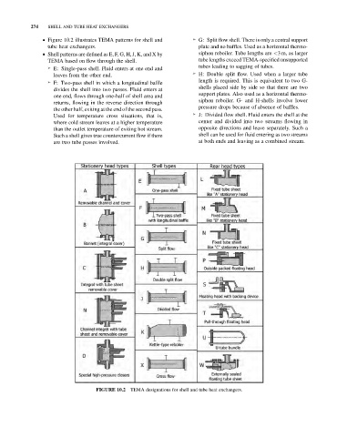
& Figure 10.2 illustrates TEMA patterns for shell and ➢ G: Split flow shell. There is only a central support
tube heat exchangers. plate and no baffles. Used as a horizontal thermo-
& Shell patterns are defined as E, F, G, H, J, K, and X by siphon reboiler. Tube lengths are <3 m, as larger
TEMA based on flow through the shell. tube lengths exceed TEMA-specified unsupported
tubes leading to sagging of tubes.
➢ E: Single-pass shell. Fluid enters at one end and
leaves from the other end. ➢ H: Double split flow. Used when a larger tube
length is required. This is equivalent to two G-
➢ F: Two-pass shell in which a longitudinal baffle
shells placed side by side so that there are two
divides the shell into two passes. Fluid enters at
support plates. Also used as a horizontal thermo-
one end, flows through one-half of shell area and
siphon reboiler. G- and H-shells involve lower
returns, flowing in the reverse direction through
pressure drops because of absence of baffles.
the other half, exiting at the end of the second pass.
Used for temperature cross situations, that is, ➢ J: Divided flow shell. Fluid enters the shell at the
where cold stream leaves at a higher temperature center and divided into two streams flowing in
than the outlet temperature of exiting hot stream. opposite directions and leave separately. Such a
Such a shell gives true countercurrent flow if there shell can be used for fluid entering as two streams
are two tube passes involved. at both ends and leaving as a combined stream.
TEMA designations for shell and tube heat exchangers.
FIGURE 10.2