
Page 298 - Fluid mechanics, heat transfer, and mass transfer
P. 298
HEAT EXCHANGERS 279
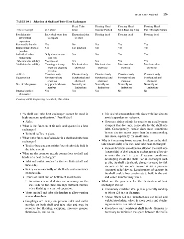
TABLE 10.1 Selection of Shell and Tube Heat Exchangers
Fixed Tube Floating Head Floating Head Floating Head
Type of Design U-Bundle Sheet Outside Packed Split-Backing Ring Pull-Through Bundle
Provision for Individual tubes free Expansion joint Floating head Floating head Floating head
differential to expand in shell
expansion
Removable bundle Yes No Yes Yes Yes
Replacement bundle Yes Not practical Yes Yes Yes
possible
Individual tubes Only those in out- Yes Yes Yes Yes
replaceable side row
Tube side cleanability Mechanical Yes Yes Yes Yes
Shell side cleanability Cleaning not easy, Mechanical or Mechanical or Mechanical or Mechanical or
chemical cleaning chemical chemical chemical chemical
possible
D-Pitch Chemical only Chemical only Chemical only Chemical only Chemical only
Square pitch Mechanical and Mechanical and Mechanical and Mechanical and Mechanical and
chemical chemical chemical chemical chemical
No. of tube passes Any practical even Normally no Normally no Normally no Normally no
number limitations limitations limitations limitations
Internal gaskets Yes Yes Yes No No
eliminated
Courtesy: GPSA Engineering Data Book, 12th edition.
. ‘‘A shell and tube heat exchanger cannot be used in & It is desirable to match nozzle sizes with line sizes to
high-pressure applications.’’ True/False? avoid expanders or reducers.
& False. & However, sizing criteria for nozzles are usually more
. What is the function of tie rods and spacers in a heat stringent than for lines, especially for the shell side
exchanger? inlet. Consequently, nozzle sizes must sometimes
be one size (or more) larger than the corresponding
& To hold baffles in place.
line sizes, especially for small lines.
. What is the function of a header in a shell and tube heat
. Why is it necessary to use vacuum breakers on the shell
exchanger?
side (steam side) of a shell and tube heat exchanger?
& To distribute and control the flow of tube side fluid in
& Vacuum breakers are often installed on the shell side
the tube circuit.
(steam side) of shell and tube exchangers to allow air
. What are the common nozzle connections to shell and
to enter the shell in case of vacuum conditions
heads of a heat exchanger?
developing inside the shell. For an exchanger such
& Inlet and outlet nozzles for the two fluids (shell and
as this, the shell side should already be rated for full
tube side).
vacuum so the vacuum breaker is not a pressure
& Safety valves normally on shell side and sometimes
(vacuum) relief device. Development of vacuum in
on tube side. the shell could allow condensate to build in the unit
& Drains on shell and on bottom of most heads. and water hammer may result.
➢ Sometimes several drains are necessary on the . What are the practices for the fabrication of heat
shell side to facilitate drainage between baffles, exchanger shells?
when flushing is a part of operation. & Commonly available steel pipe is generally used up
& Vents on shell and tube side headers to allow venting to 60 cm (24 in.) in diameter.
noncondensables. & Above 60 cm (24 in.), manufactures use rolled and
& Couplings are handy on process inlet and outlet welded steel plate, which is more costly and obtain-
nozzles on both shell and tube side and may be ing roundness is a critical issue.
required for flushing, sampling, pressure gauges, & Roundness and consistent shell inside diameter is
thermowells, and so on. necessary to minimize the space between the baffle