
Page 303 - Fluid mechanics, heat transfer, and mass transfer
P. 303
SHELL AND TUBE HEAT EXCHANGERS
284
& Other Liquids:
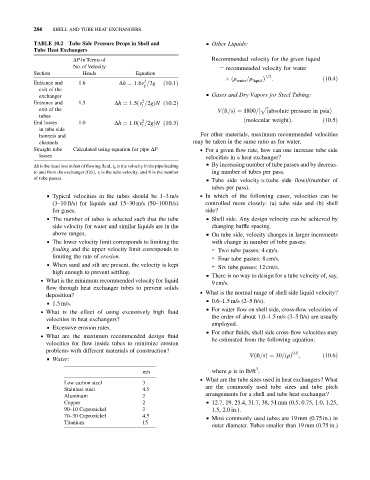
TABLE 10.2 Tube Side Pressure Drops in Shell and
Tube Heat Exchangers
DP in Terms of Recommended velocity for the given liquid
No. of Velocity ¼ recommended velocity for water
Section Heads Equation 1=2
ðr =r Þ : ð10:4Þ
2
Entrance and 1.6 Dh ¼ 1:6v =2g ð10:1Þ water liquid
p
exit of the
exchanger & Gases and Dry Vapors for Steel Tubing:
2
Entrance and 1.5 Dh ¼ 1:5ðv =2gÞN ð10:2Þ
t
exit of the p ffiffi
Vðft=sÞ¼ 1800=½ ðabsolute pressure in psiaÞ
tubes
2
End losses 1.0 Dh ¼ 1:0ðv =2gÞN ð10:3Þ ðmolecular weightÞ: ð10:5Þ
t
in tube side
bonnets and For other materials, maximum recommended velocities
channels may be taken in the same ratio as for water.
Straight tube Calculated using equation for pipe DP . For a given flow rate, how can one increase tube side
losses velocities in a heat exchanger?
& By increasing number of tube passes and by decreas-
Dh is the head loss in feet offlowing fluid, v p is thevelocity in the pipe leading
to and from the exchanger (ft/s), v t is the tube velocity, and N is the number ing number of tubes per pass.
of tube passes.
& Tube side velocity / (tube side flow)/(number of
tubes per pass).
& Typical velocities in the tubes should be 1–3 m/s . In which of the following cases, velocities can be
(3–10 ft/s) for liquids and 15–30 m/s (50–100 ft/s) controlled more closely: (a) tube side and (b) shell
for gases. side?
& The number of tubes is selected such that the tube & Shell side. Any design velocity can be achieved by
side velocity for water and similar liquids are in the changing baffle spacing.
above ranges. & On tube side, velocity changes in larger increments
& The lower velocity limit corresponds to limiting the with change in number of tube passes:
fouling and the upper velocity limit corresponds to ➢ Two tube passes: 4 cm/s.
limiting the rate of erosion. ➢ Four tube passes: 8 cm/s.
& When sand and silt are present, the velocity is kept
➢ Six tube passes: 12 cm/s.
high enough to prevent settling.
& There is no way to design for a tube velocity of, say,
. What is the minimum recommended velocity for liquid
9 cm/s.
flow through heat exchanger tubes to prevent solids
. What is the normal range of shell side liquid velocity?
deposition?
& 0.6–1.5 m/s (2–5 ft/s).
& 1.5 m/s.
& For water flow on shell side, cross-flow velocities of
. What is the effect of using excessively high fluid
the order of about 1.0–1.5 m/s (3–5 ft/s) are usually
velocities in heat exchangers?
employed.
& Excessive erosion rates.
& For other fluids, shell side cross-flow velocities may
. What are the maximum recommended design fluid
be estimated from the following equation:
velocities for flow inside tubes to minimize erosion
problems with different materials of construction? 0:5
Vðft=sÞ¼ 30=ðrÞ ; ð10:6Þ
& Water:
3
m/s where r is in lb/ft .
. What are the tube sizes used in heat exchangers? What
Low carbon steel 3
are the commonly used tube sizes and tube pitch
Stainless steel 4.5
Aluminum 2 arrangements for a shell and tube heat exchanger?
Copper 2 & 12.7, 19, 25.4, 31.7, 38, 51 mm (0.5, 0.75, 1.0, 1.25,
90–10 Cupronickel 3 1.5, 2.0 in.).
70–30 Cupronickel 4.5 & Most commonly used tubes are 19 mm (0.75 in.) in
Titanium 15
outer diameter. Tubes smaller than 19 mm (0.75 in.)