
Page 299 - Fluid mechanics, heat transfer, and mass transfer
P. 299
SHELL AND TUBE HEAT EXCHANGERS
280
outside edge and the shell as excessive space allows & Properly rolled joints have uniform tightness to
fluid bypass and reduced performance. minimize tube fractures, stress corrosion, and tube
& Roundness can be increased by expanding the shell sheet deformation.
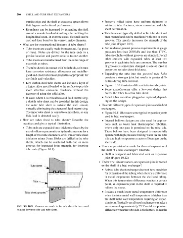
around a mandrel or double rolling after welding the & Tube holes are typically drilled in the tube sheet and
longitudinal seam. In extreme cases, the shell can be then reamed and can be machined with one or more
cast and then bored to the correct inside diameter. grooves. This greatly increases the strength of the
. What are the constructional features of tube sheets? tube joint (Figure 10.9).
& Tube sheets are usually made from a round, flat piece & For moderate general process requirements at gauge
of metal. Holes are drilled for the tube ends in a pressures less than 2058 kPa and less than 177 C,
precise location and pattern relative to one another. tube sheet holes without grooves are standard. For all
other services with expanded tubes at least two
& Tube sheets are manufactured from the same range of
grooves in each tube hole are common. The number
materials as tubes.
of grooves is sometimes changed to one or three in
& The tube sheet is in contact with both fluids, so it must
proportion to tube sheet thickness.
have corrosion resistance allowances and metallur-
& Expanding the tube into the grooved tube holes
gical and electrochemical properties appropriate for
provides a stronger joint but results in greater diffi-
the fluids and velocities.
culties during tube removal.
& Low carbon steel tube sheets can include a layer of
& Figure 10.10 illustrates different tube-to-tube joints.
a higher alloy metal bonded to the surface to provide
more effective corrosion resistance without the & Some manufacturers offer a low-cost design that
expense of using the solid alloy. brazes the tubes to a thin tube sheet.
& In cases where it is critical to avoid fluid intermixing, & Failed tubes are either plugged or replaced, depend-
a double tube sheet can be provided. In this design, ing on the design.
the outer tube sheet is outside the shell circuit, . Illustrate different types of expansion joints used in heat
virtually eliminating the chance of fluid intermixing. exchangers.
The inner tube sheet is vented to atmosphere, so any & Figure 10.11 illustrates some typical expansion joints
fluid leak is detected easily. used in heat exchangers.
. How are tubes fixed to tube sheets? Describe the & Internal bellows designs are also used for applica-
practices and give a typical illustration. tions such as waste heat thermosiphon reboilers,
& Tube ends are expanded onto thick tube sheets by the where only one pass is permitted on the tube side.
use of rollers or pneumatic or hydraulic pressure for a These bellows have been designed to successfully
length of two tube diameters, or 50 mm or tube sheet operate with high-pressure boiling water on the tube
thickness minus 3 mm. Holes are drilled in the tube side and high-temperature reactor effluent gas on the
sheets, which can be machined with one or more shell side.
grooves for increased joint strength, for inserting . How can provision be made for thermal expansion of
tube ends (Figure 10.9). the shell of a heat exchanger? Illustrate.
& Shell is designed and fabricated with an expansion
joint (Figure 10.12).
. Under what circumstances, an expansion joint is needed
on the shell of a heat exchanger?
& A fixed tube sheet exchanger does not have provision
for expansion of the tubing when there is a difference
in metal temperature between the shell and tubing.
When this temperature difference reaches a certain
point, an expansion joint in the shell is required to
relieve the stress.
& It takes a much lower metal temperature difference
when the tube metal wall temperature is higher than
the shell metal wall temperature requiring an expan-
sion joint. Typically an all steel exchanger can take a
Grooves are made in the tube sheet for increased maximum of approximately 25 C metal temperature
FIGURE 10.9
jointing between tube and tube sheet. difference when the tube side is the hottest. When the