
Page 295 - Fluid mechanics, heat transfer, and mass transfer
P. 295
SHELL AND TUBE HEAT EXCHANGERS
276
FIGURE 10.5 2–4 Floating head heat exchanger with baffles.
& In a floating head heat exchanger, one tube sheet is
fixed relative to the shell and the other is free to float
within the shell. This permits free expansion of the
tube bundle (Figures 10.4 and 10.5).
& Floating head heat exchanger is the most versatile
type of shell and tube heat exchanger and also the
costliest.
& Shell circuit can be inspected and cleaned with steam
or mechanically.
& The tube bundle can be repaired or replaced without
disturbing the shell.
U-bundle heat exchanger with baffles.
FIGURE 10.6
& Provides maximum surface for a given shell diameter
for removable bundle design.
& There are various types of floating head construction.
limited to clean fluids. Chemical cleaning may be
The most common ones are the pull-through type
used.
with backing device, TEMA S (Figure 10.4) and pull-
& Can be designed for single and multiple tube passes
through TEMA T (Figure 10.7) designs.
to assure proper velocity.
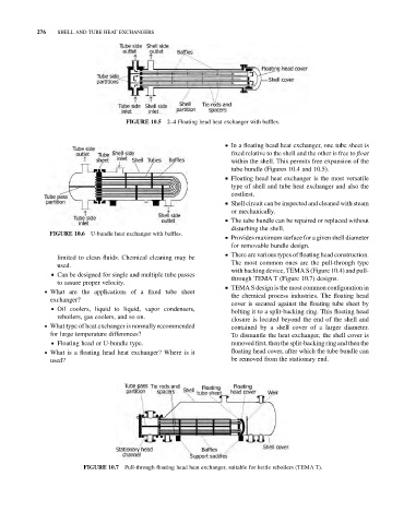
& TEMA S design is the most common configuration in
. What are the applications of a fixed tube sheet
the chemical process industries. The floating head
exchanger?
cover is secured against the floating tube sheet by
& Oil coolers, liquid to liquid, vapor condensers,
bolting it to a split-backing ring. This floating head
reboilers, gas coolers, and so on.
closure is located beyond the end of the shell and
. What type of heat exchanger is normally recommended contained by a shell cover of a larger diameter.
for large temperature differences? To dismantle the heat exchanger, the shell cover is
& Floating head or U-bundle type. removed first, then the split-backing ring and then the
. What is a floating head heat exchanger? Where is it floating head cover, after which the tube bundle can
used? be removed from the stationary end.
FIGURE 10.7 Pull-through floating head heat exchanger, suitable for kettle reboilers (TEMA T).