
Page 332 - Fluid mechanics, heat transfer, and mass transfer
P. 332
HEAT EXCHANGERS 313
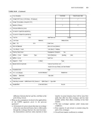
TABLE 10.10 (Continued)
2 3 d i u l F o l l A o i t a c n S h l l e d i S e T u b C / e h a n n l e d i S e
24 Design/Test Pressure (min/max), kPa (gauge) / /
25 Design Temperature, (max/min) (ºC)
2 6 Number of Passes 1 2
2 7 Corrosion Allowance (mm)
2 8 C o n n o i t c e n n I p t u e z i S a n d R n i t a g
2 9 C o n n o i t c e n O p t u t u e z i S a n d R n i t a g
3 0 T u b e N . o O . D . W l l a T k c i h n s s e L e n h t g
3 1 T u b e T y p e M : l a i r e t a P c t i P / n r e t t a h:
32 Shell I.D. O.D. Shell Cover
3 3 C h a n n l e M : l a i r e t a C h a n n l e C o v r e M a i r e t a l:
3 4 Tube Sheet — Fixed: Tube Sheet — Floating:
3 5 o l F n i t a g H e a d C o v r e I m n i p g e m e t n o i t c e t o r P n Y s e
37 Baffles — Cross Material Type %Cut (Dia/Area) Spacing Inlet
3 8 Baffles — Long S e l a T y p e
3 9 Supports — Tube U B - e n d T y p e
4 0 B y p s s a S e l a a r r A n g e m e t n Tube-to-Tube Sheet Joint
Double Grooved, Rolled, and Seal Welded
4 1 E x p a n o i s n t n i o J T y p e
2
42 P v — Inlet Nozzle B u n e l d E a r t n n e c B u n e l d E t i x
43 Gaskets S h l l e d i S e T u b e d i S e
44 Floating Head
45 Code Requirements — ASME Section VIII, Division 1 TEMA Class C — Type NEN
4 6 W g i e S / t h h l l e Filled with Water B u n e l d
difference between the hot and the cold fluid at the transfer. In actual situation, there will be some flow
point being viewed. paths that offer less flow resistance and less heat
. What are the assumptions involved in the applicability transfer surface than others, resulting in less heat
of the LMTD equations given in the previous transfer.
questions? & The heat exchanger operates under steady-state
& All elements of a given stream that enter an exchang- conditions.
er have the same thermal history, that is, follow paths & Heat capacity of each stream is constant along the
through the exchanger that have the same heat trans- path of the exchanger.
fer characteristics and have same exposure to heat & Overall heat transfer coefficient is constant.