
Page 335 - Fluid mechanics, heat transfer, and mass transfer
P. 335
SHELL AND TUBE HEAT EXCHANGERS
316
series, and the parameters, R and P, as defined in the & The following equations, amenable for use by cal-
following relationships: culators, can be used in place of the charts, for the
estimation of F values:
R ¼ðT 1 T 2 Þ=ðt 2 t 1 Þ
p 2
¼ðtemperature range of the shell side fluidÞ= F 1 2 ¼f½ ðR þ1Þ=ðR 1Þln½ð1 PÞ=ð1 PRÞg=
ðtemperature range of the tube side fluidÞ: p 2 p 2
lnf½Aþ ðR þ1Þ=½A ðR þ1Þg: ð10:29Þ
ð10:27Þ
➢ In other words, R is the ratio of the fall in p 2
F 2 4 ¼f½ ðR þ1Þ=2ðR 1Þln½ð1 PÞ=ð1 PRÞg=
temperature of the hot fluid to the rise in temper-
p 2 p 2
ature of the cold fluid. lnf½AþBþ ðR þ1Þ=½AþB ðR þ1Þg;
➢ R is called heat capacity rate ratio and its value
ð10:30Þ
ranges from 0 to ¥, zero being for pure vapor
condensation and infinity being for pure liquid where
vaporization. p
A ¼ð2=PÞ 1 R and B ¼ð2=PÞ ð1 PÞð1 PRÞ:
P ¼ðt 2 t 1 Þ=ðT 1 t 1 Þ
ð10:31Þ
¼ðtemperature range of tube side fluidÞ=
F 1–2 stands for F value for a 1–2 exchanger and F 2–4
ðmaximum temperature differenceÞ: stands for F for a 2–4 exchanger.
ð10:28Þ ➢ The equation given for F 1–2 also applies to one
➢ P, in other words, is the heat transfer (or thermal) shell pass and two, four, or any multiple of two
effectiveness, which is the ratio of actual temper- tube passes.
ature rise of the cold fluid to the maximum tem- ➢ Similarly, the equation for F 2–4 also applies to two
perature rise obtainable, that is, if the warm end shell passes and four,eight, or anymultipleoffour
approach is zero, based on countercurrent flow. tube passes.
➢ The value of P ranges from 0 to 1. . What value of LMTD correction factor is generally
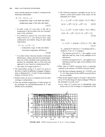
& The relationships among F, R, and P are given in assumed in the absence of LMTD correction charts?
the form of charts for different exchanger configura- & For the heat exchanger equation, Q ¼ UAFDT lm , use
tions as illustrated for 1–2 and 2–4 heat exchangers F ¼ 0.9 when charts for the LMTD correction factor
(Figures 10.40 and 10.41). are not available.
& Similar charts are given in standard texts for other . What are the negative aspects of using F values below
exchanger configurations. 0.8 or 0.75 in the design of a heat exchanger? What are
& Once the terminal temperatures of both streams of the alternatives in such cases?
the exchanger are specified/determined, R, P, and & Low value of F means use of substantially large
LMTD can be calculated. surface area for the exchanger to compensate for the
FIGURE 10.40 LMTD correction factors, F, for a 1–2 heat exchanger.