
Page 336 - Fluid mechanics, heat transfer, and mass transfer
P. 336
HEAT EXCHANGERS 317
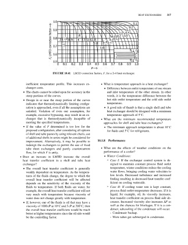
FIGURE 10.41 LMTD correction factors, F, for a 2–4 heat exchanger.
inefficient temperature profile. This increases ex- . What is temperature approach in a heat exchanger?
changer costs. & Difference between outlet temperature of one stream
& The charts cannot be relied upon for accuracy in the and inlet temperature of the other stream. In other
steep portions of the curves. words, it is the temperature difference between the
& Design in or near the steep portion of the curves hot side outlet temperature and the cold side outlet
indicates that thermodynamically limiting configu- temperature.
ration is approached, even if all the assumptions are & A good rule of thumb is that a single shell and tube
satisfied. Violation of even one assumption, for heat exchanger should be designed with a minimum
example, excessive bypassing, may result in an ex- temperature approach of 5 C.
changer that is thermodynamically incapable of . What are the minimum recommended temperature
meeting the specified temperatures. approaches for shell and tube heat exchangers?
& If the value of F determined is too low for the & The minimum approach temperature is about 10 C
proposed configuration, after considering all options for fluids and 5 C for refrigerants.
of shell and tube passes by using relevant charts, use
of additional shells in series might be considered for
improvement. Alternatively, it may be possible to 10.1.8 Performance
redesign the exchangers to permit the use of fixed
tube sheet exchangers and purely countercurrent . What are the effects of weather conditions on the
flow, for which F is unity. performance of a cooler?
. Does an increase in LMTD increase the overall & Winter Conditions:
heat transfer coefficient in a shell and tube heat ➢ Case I: If the exchanger control system is de-
exchanger? signed to maintain constant process fluid outlet
& The overall heat transfer coefficient is generally temperature, winter conditions reduce the cooling
weakly dependent on temperature. As the tempera- water flows, bringing cooling water velocities to
tures of the fluids change, the degree to which the low levels. Decreased turbulence and increased
overall heat transfer coefficient will be affected fouling resulting in decreased heat transfer coef-
depends on the sensitivity of the viscosity of the ficient on cooling waterside.
fluids to temperature. If both fluids are water, for ➢ Case II: If cooling water rate is kept constant,
example, the overall heat transfer coefficient will not process fluid outlet temperature decreases. If it is
vary much with temperature because viscosity of liquid, for example, oil, its viscosity increases,
water does not change greatly with temperature. heat transfer coefficient on process fluid side de-
& If, however, one of the fluids is oil that may have a creases. Increased viscosity also increases DP as
viscosity of 1000 cP at 10 C and 5 cP at 200 C, then well as the chances for blockages. If it is a con-
the overall heat transfer coefficient would be much denser, subcooling of the condensate will occur.
better at higher temperatures since the oil side would - Condensate backup.
be the controlling factor. - More tubes get submerged in condensate.