
Page 351 - Fluid mechanics, heat transfer, and mass transfer
P. 351
CONDENSERS 333
& Condensate at bubble point may create NPSH & Design of condensate control valve should take into
problems for the condensate outlet pump, that is, consideration the amount of flashing that is likely to
enough NPSH may not be there, resulting in cavita- occur, giving rise to two-phase flow.
tion, etc. & Condensate receivershould be locatedwell below the
. What is condensate depression? How does it decrease level of bottom tube sheet, in case of a vertical
efficiency of a power plant? thermosiphon reboiler, or below the lowest possible
& The difference between the saturation temperature at point of the reboiler, making condensate outlet line as
the existing condenser vacuum and the temperature large as possible to assist gravity flow. It must be
of the condensate is termed condensate depression. ensured that no condensate accumulates around the
This is expressed as a number of degrees condensate tube bundle of the reboiler.
depression or degrees subcooled. & The condensate receiver should have adequate con-
& Excessive condensate depression decreases the op- densate inventory to provide for positive control,
erating efficiency of the plant because the subcooled operability, maintenance and space requirements.
condensate must be reheated in the boiler, which in The vessel is normally sized for an L/D ratio of
turn requires more heat from the fuel or other heat 2.5–3.0.
source. & Illustrate stratified and annular flows for the case of
. Suggest a suitable way to remove condensate from a vapors condensing in a horizontal tube.
reboiler involving high flows of condensate. & Stratified and annular flows for vapors condensing
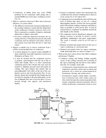
& A typical diagram of a typical system adoptable to inside horizontal tubes are shown in Figure 11.3.
large condensate removable capacities is given as an . What are the most serious factors that affect condenser
illustration in Figure 11.2. performance? Explain.
& It must be ensured that the condensate receiver & Condenser scaling and fouling. Scaling normally
is properly vapor-balanced with the top of the re- occurs on the cooling waterside and is possible on
boiler tube bundle. This is to allow unrestricted the vapor condensing side also due to water infiltra-
condensate gravity flow. Proper line sizes must be tion into, for example, steam side.
ensured to minimize pressure drop and permit for ➢ Cooling waters contain hardness ions, calcium and
venting. The vapor balance line ensures that no magnesium, and other cations such as sodium and
noncondensables will collect at the top of the con- potassium, all of which are counter-balanced by
densate receiver and stop the gravity flow of con- bicarbonate, chloride, and sulfate anions.
densate. Steam chest around the tube bundle must be
➢ Groundwaters usually contain higher concentra-
provided for purging of all noncondensables, by the
tions of dissolved ions, while surface waters are
use of adequate line sizes of not less than 2.5 cm to
often softer but typically contain suspended solids,
provide enough vent capacity and mechanical
organic compounds, and microorganisms. Silica is
rigidity.
another problematic contaminant, which in some
FIGURE 11.2 Condensate removal system for a reboiler.