
Page 354 - Fluid mechanics, heat transfer, and mass transfer
P. 354
HEAT TRANSFER EQUIPMENT INVOLVING PHASE TRANSFER
336
vacuum and exchanger failure becomes a possibility. & For those installations where cooling water sources
This problem gets aggravated, especially for large produce rapid fouling of the tubes, a higher factor
diameter shells when condensing fluid is on the shell must be used.
side. . What are the effects of weather on condenser duties?
. What is the generally recommended temperature ap- & Can limit production in summer.
proach in steam condensers in air conditioning and & Capable of condensing more vapor at night than
power plants?
during day. This situation will be more pronounced
& Lowest feasible approach (steam condensing tem-
in plants located in desert atmospheres.
perature minus entering cooling water temperature) . “When light components accumulate, condensation is
is 3 C.
impeded.” True/False? Explain.
& Generally the approach used in most air conditioning
& True. Presence of light components and/or noncon-
installations is 10 C but not less than 5 C, to save on
densables reduce condenser capacity due to reduced
costs involved in large heat transfer surface
heat transfer coefficients.
requirements.
& Solution for this problem is to vent
. What is meant by cleanliness factor?
noncondensables.
& Cleanliness factor is defined as 100 (U Design /
. “Condensation inside tubes is not appropriate for vac-
U Clean ).
uum column overhead condenser because ....”
. What is the normally recommended cleanliness factor Comment.
for the design of condensers for air conditioning and & This statement is true because of the high tube side
power plants?
DP and the difficulty in piping and supporting a
& Most surface condensers for air conditioning and
vertically mounted condenser. Therefore, condensa-
power plant applications are designed with a clean- tion is the best choice.
liness factor of 85%. This means that the heat transfer . Summarize troubleshooting of vacuum condensers.
rate used in designing the condenser is 85% of the
& Table 11.1 gives condenser troubleshooting.
clean heat transfer coefficient.
& For most applications using clean cooling tower
water, refrigeration condensers should be specified 11.2 REBOILERS
with a fouling factor of 0.0005 and steam surface
. Name common types of reboilers.
condensers designed for an 85% clean tube
coefficient. & Natural circulation reboilers
& If the refrigerant fouling factor is increased, ➢ Once-through reboiler.
the surface condenser cleanliness factor should be ➢ Recirculation reboiler.
increased by the same percentage. Thus, if the re- & Forced circulation reboilers.
frigerant condenser is specified as 0.001 versus
& Vertical thermosiphon reboilers.
0.0005, the corresponding cleanliness factor
& Horizontal thermosiphon reboilers.
for the surface condenser is 70% clean versus
85% clean. & Flooded bundle reboilers.
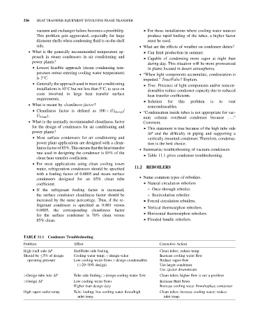
TABLE 11.1 Condenser Troubleshooting
Problem Effect Corrective Action
High shell side DP Shell/tube side fouling Clean tubes; reduce temp.
Should be 5% of design Cooling water temp. > design value Increase cooling water flow
operating pressure Low cooling water flows > design condensables Reduce vapor flow
(>20–30% design) Use larger condenser
Use ejector downstream
>Design tube side DP Tube side fouling; >design cooling water flow Clean tubes; higher flow is not a problem
>Design DT Low cooling water flows Increase fluid flows
Higher than design duty Increase cooling water flows/replace condenser
High vapor outlet temp. Tube fouling; low cooling water flows/high Clean tubes; increase cooling water; reduce
inlet temp. inlet temp.