
Page 78 - Fluid mechanics, heat transfer, and mass transfer
P. 78
VALVES 55
➢ Rated capacity is usually attained at 25% Once the line is pressurized, this type of valve cannot
overpressure. reopen to remove air that may subsequently accu-
& Safety relief valve is an automatic pressure actuated mulate until the pressure becomes negative, allowing
relievingdevicesuitableforuseeitherasasafetyvalve the float to drop. If the pressure becomes negative
or as a relief valve, depending on the application. during a transient or while draining, the float drops
➢ It is characterized by an adjustment to allow and admits air into the line.
reclosure, either a popup or a nonpopup action & Air release valves contain a small orifice and are
and a nozzle-type entrance. designed to release small quantities of pressurized air
trapped during filling the small orifice is controlled
➢ Opens in proportion to increase in internal
by a plunger activated by a float at the end of a lever
pressure.
arm. As air accumulates in the valve body, the float
➢ It reseats as pressure drops.
drops and opens the orifice. As the air is expelled, the
➢ Used on steam, gas, vapor and liquid (with
float rises and closes off the orifice.
adjustments).
. What are the desirable characteristics for the selection
➢ Most general type in petroleum and petrochemical
of a valve for flow control?
plants.
& For many flow control applications, it is desirable to
➢ Rated capacity is reached at 3% or 10% overpres-
select a valve that has linear control characteristics.
sure,dependingoncodeand/orprocess conditions.
This means that if you close the valve 10%, the flow
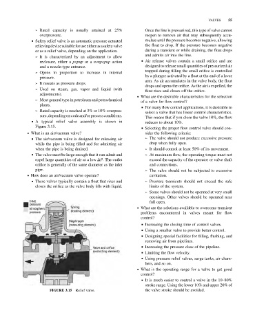
& A typical relief valve assembly is shown in
reduces to about 10%.
Figure 3.15. & Selecting the proper flow control valve should con-
. What is an air/vacuum valve? sider the following criteria:
& The air/vacuum valve is designed for releasing air ➢ The valve should not produce excessive pressure
while the pipe is being filled and for admitting air drop when fully open.
when the pipe is being drained. ➢ It should control at least 50% of its movement.
& The valve must be large enough that it can admit and ➢ At maximum flow, the operating torque must not
expel large quantities of air at a low DP. The outlet exceed the capacity of the operator or valve shaft
orifice is generally of the same diameter as the inlet and connections.
pipe. ➢ The valve should not be subjected to excessive
. How does an air/vacuum valve operate? cavitation.
& These valves typically contain a float that rises and ➢ Pressure transients should not exceed the safe
closes the orifice as the valve body fills with liquid. limits of the system.
➢ Some valves should not be operated at very small
openings. Other valves should be operated near
full open.
. What are the solutions available to overcome transient
problems encountered in valves meant for flow
control?
& Increasing the closing time of control valves.
& Using a smaller valve to provide better control.
& Designing special facilities for filling, flushing, and
removing air from pipelines.
& Increasing the pressure class of the pipeline.
& Limiting the flow velocity.
& Using pressure relief valves, surge tanks, air cham-
bers, and so on.
. What is the operating range for a valve to get good
control?
& It is much easier to control a valve in the 10–80%
stroke range. Using the lower 10% and upper 20% of
FIGURE 3.15 Relief valve. the valve stroke should be avoided.