
Page 83 - Fluid mechanics, heat transfer, and mass transfer
P. 83
FLOW MEASUREMENT
60
Turndown ratios.
FIGURE 4.1
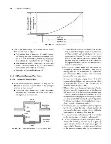
. How is full flow through a flow meter ensured during ➢ All DP primary elements restrict the flow in some
flow measurement in a pipe? way. A restriction in a pipe results in an increase in
& Full conduit flow is important in liquid systems. the fluid velocity, according to Bernoulli’s law of
The flowing pipe must run full, or measurements made conservation of energy. The ensuing conversion to
will be in error. This can be a problem if piping design kinetic energy reduces the static pressure. This
does not keep the meter below the rest of the piping. pressure drop, the measured DP, is proportional to
the square root of the flow rate and thus provides a
& If the meter is at the high point, vapor can collect and
means to measure flow.
create a void in the meter so any velocity or volume
displacement measured will be in error. & Orifice meter, venturi meter, and flow nozzle are
examples of obstruction flow meters. They have no
& This point is illustrated in Figure 4.2.
moving parts and can be fabricated in a wide selec-
tion of materials. Their purchase cost is relatively
low, even for large pipe sizes.
4.1.1 Differential Pressure Flow Meters
4.1.1.1 Orifice and Venturi Meters & Accuracy is moderate, ranging from 1% to 5%;
compensation techniques can improve these values
. What are obstruction flow meters? Are they same as to better than 1%. DP meters are generally easy to
differential pressure meters? What is the principle select for a specific application.
involved in these meters? & When the flow area changes abruptly, the effective
& Obstruction flow meters, also called differential flow area immediately downstream of the alteration
pressure (DP) flow meters, are based on the differ- will not necessarily be the same as the pipe flow area.
ential pressure measurements. This effect is brought about by an inability of a fluid
to expand immediately upon encountering an expan-
sion as a result of the inertia of each fluid particle.
This forms a central core flow bounded by regions of
slower moving recirculating eddies.
& As a consequence, the pressure sensed with pipe wall
taps located within the vena contracta region will
correspond to the higher moving velocity within the
vena contracta of unknown flow area, A 2 .
& The unknown vena contracta area will be accounted
for by introducing a contraction coefficient, C c .
& The low pressure at the point of highest velocity
creates the possibility for the liquid to partially
vaporize (called flashing). It might remain partially
vaporized after the meter or it might return to a liquid
Meter installations for gas and liquid flows. as the pressure increases after the lowest pressure
FIGURE 4.2