
Page 132 - Subyek Teknik Mesin - Forsthoffers Best Practice Handbook for Rotating Machinery by William E Forsthoffer
P. 132
Be st Practice 3 .2 Compressor Best Practices
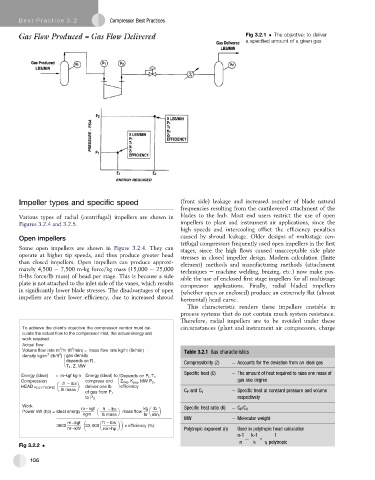
Fig 3.2.1 The objective: to deliver
a specified amount of a given gas
Impeller types and specific speed (front side) leakage and increased number of blade natural
frequencies resulting from the cantilevered attachment of the
Various types of radial (centrifugal) impellers are shown in blades to the hub. Most end users restrict the use of open
Figures 3.2.4 and 3.2.5. impellers to plant and instrument air applications, since the
high speeds and intercooling offset the efficiency penalties
Open impellers caused by shroud leakage. Older designs of multistage cen-
trifugal compressors frequently used open impellers in the first
Some open impellers are shown in Figure 3.2.4. They can
stages, since the high flows caused unacceptable side plate
operate at higher tip speeds, and thus produce greater head stresses in closed impeller design. Modern calculation (finite
than closed impellers. Open impellers can produce approxi- element) methods and manufacturing methods (attachment
mately 4,500 e 7,500 m-kg force/kg mass (15,000 e 25,000 techniques e machine welding, brazing, etc.) now make pos-
ft-lbs force/lb mass) of head per stage. This is because a side sible the use of enclosed first stage impellers for all multistage
plate is not attached to the inlet side of the vanes, which results compressor applications. Finally, radial bladed impellers
in significantly lower blade stresses. The disadvantages of open (whether open or enclosed) produce an extremely flat (almost
impellers are their lower efficiency, due to increased shroud horizontal) head curve.
This characteristic renders these impellers unstable in
process systems that do not contain much system resistance.
Therefore, radial impellers are to be avoided under these
To achieve the client's objective the compressor vendor must cal- circumstances (plant and instrument air compressors, charge
culate the actual flow to the compressor inlet, the actual energy and
work required.
Actual flow
Volume flow rate m /hr (ft /min) = mass flow rate kg/hr (lb/min) × Table 3.2.1 Gas characteristics
3
3
3
3
density kg/m (lb/ft ) gas density
depends on P 1 , Compressibility (Z) Accounts for the deviation from an ideal gas
T 1 ,Z, MW
Specific heat (C) The amount of heat required to raise one mass of
Energy (ideal) = m-kgf kgm Energy (ideal) to Depends on P 1 ,T 1 ,
Compression compress and Z avg ,K avg ,MW P 2 , gas one degree
ft lbs
HEAD POLYTROPIC deliver one lb efficiency
lb mass C P and C V Specific heat at constant pressure and volume
of gas from P 1
respectively
to P 2
Work Specific heat ratio (K)
m kgf ft – lbs kg lb C P /C V
–
Power kW (hp) = ideal energy mass flow
kgm lb mass hr min
MW Molecular weight
m kgf ft lbs
–
3600 33, 000 x efficiency (%)
hr kW min-hp Polytropic exponent (n) Used in polytropic head calculation
–
n-1 k-1 1
n ¼ k h polytropic
Fig 3.2.2
106