
Page 137 - Subyek Teknik Mesin - Forsthoffers Best Practice Handbook for Rotating Machinery by William E Forsthoffer
P. 137
Compressor Best Practices Be st Practice 3.3
is shown in Figure 3.3.2. Note that this type of compressor can
be either horizontally or radially split.
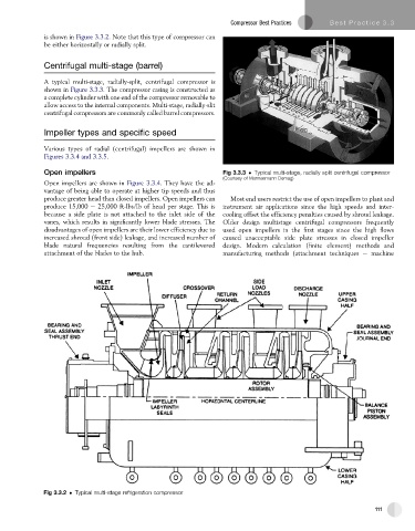
Centrifugal multi-stage (barrel)
A typical multi-stage, radially-split, centrifugal compressor is
shown in Figure 3.3.3. The compressor casing is constructed as
a complete cylinder with one end of the compressor removable to
allow access to the internal components. Multi-stage, radially-slit
centrifugal compressors are commonly called barrel compressors.
Impeller types and specific speed
Various types of radial (centrifugal) impellers are shown in
Figures 3.3.4 and 3.3.5.
Open impellers Fig 3.3.3 Typical multi-stage, radially split centrifugal compressor
(Courtesy of Mannesmann Demag)
Open impellers are shown in Figure 3.3.4. They have the ad-
vantage of being able to operate at higher tip speeds and thus
produce greater head than closed impellers. Open impellers can Most end users restrict the use of open impellers to plant and
produce 15,000 e 25,000 ft-lbs/lb of head per stage. This is instrument air applications since the high speeds and inter-
because a side plate is not attached to the inlet side of the cooling offset the efficiency penalties caused by shroud leakage.
vanes, which results in significantly lower blade stresses. The Older design multistage centrifugal compressors frequently
disadvantages of open impellers are their lower efficiency due to used open impellers in the first stages since the high flows
increased shroud (front side) leakage, and increased number of caused unacceptable side plate stresses in closed impeller
blade natural frequencies resulting from the cantilevered design. Modern calculation (finite element) methods and
attachment of the blades to the hub. manufacturing methods (attachment techniques e machine
Fig 3.3.2 Typical multi-stage refrigeration compressor
111