
Page 136 - Subyek Teknik Mesin - Forsthoffers Best Practice Handbook for Rotating Machinery by William E Forsthoffer
P. 136
Be st Practice 3 .3 Compressor Best Practices
B:H:P: ¼ G:H:P: þ Mechanical losses a low pressure compressor. The Fan Laws are presented in
The mechanical losses are the total of bearing, seal and Figure 3.2.8.
windage (disc friction) losses and are provided by the com- As shown, if the speed is changed, the flow, head and
pressor vendor. For estimating purposes, a conservative value of horsepower vary by the first, second and third power of speed
mechanical losses for one centrifugal or axial compressor case ratio respectively.
The reader must be cautioned however that the Fan Laws are
would be 112 kW (150 H.P.).
only an approximation; hence they should only be used as an
The Fan Laws estimating tool. Their accuracy decreases significantly with in-
These familiar relationships, sometimes called the affinity laws creasing gas molecular weight and increase in the number of
for pumps were originally derived for a single stage fan which is compression stages.
Best Practice 3.3Practice 3.3Practice 3.3
Best
Best
Pre-select centrifugal compressor casing type, impeller Lessons Learned
type, the number of compressor cases and impellers in There are many case histories of failure because centrif-
each casing. ugal compressors were not selected using the proper case
Pre-selection of centrifugal compressor casing type and impellers design and limiting the number of impellers per stage.
ensures optimum safety and reliability.
Determine if a horizontal split casing or vertical (barrel) type is re-
quired based on process conditions and vendor/company/industry Benchmarks
guidelines and plant lessons learned. I have used this best practice since the mid-1970s to achieve success
Determine the impeller type (opened or closed) base on company/ in all centrifugal compressor installations resulting in plant installations
industry guidelines and plant lessons learned. of greater than 99.7% centrifugal compressor reliability, without:
Determine the number of impellers allowed in each casing based on Critical speed issues
head per impeller stage limits and shaft stiffness (see B.P.s 3.9 and Gas instabilities (gas whirl and whip)
3.18). Impeller failures
Excessive factory acceptance test (FAT) time.
B.P. 3.3. Supporting Material
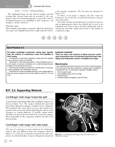
Centrifugal multi-stage horizontal split
A typical multi-stage horizontally split centrifugal compressor is
shown in Figure 3.3.1. The casing is divided into upper and
lower halves along the horizontal centerline of the compressor.
The horizontal split casing allows access to the internal com-
ponents of the compressor without disturbing the rotor to casing
clearances or bearing alignment. If possible, piping nozzles
should be mounted on the lower half of the compressor casing to
allow disassembly of the compressor without removal of the
process piping.
Centrifugal multi-stage with side loads
This type of compressor is used exclusively for refrigeration
services. The only difference from the compressor shown in
Figure 3.3.1 is that gas is induced or removed from the com-
Fig 3.3.1 Centrifugal multi-stage horizontal split (Courtesy of
pressor via side load nozzles. A typical refrigeration compressor Mannesmann Demag)
110