
Page 139 - Subyek Teknik Mesin - Forsthoffers Best Practice Handbook for Rotating Machinery by William E Forsthoffer
P. 139
Compressor Best Practices Be st Practice 3.3
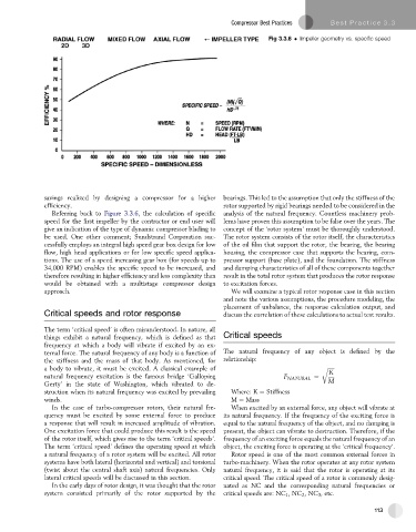
Fig 3.3.6 Impeller geometry vs. specific speed
savings realized by designing a compressor for a higher bearings. This led to the assumption that only the stiffness of the
efficiency. rotor supported by rigid bearings needed to be considered in the
Referring back to Figure 3.3.6, the calculation of specific analysis of the natural frequency. Countless machinery prob-
speed for the first impeller by the contractor or end user will lems have proven this assumption to be false over the years. The
give an indication of the type of dynamic compressor blading to concept of the ‘rotor system’ must be thoroughly understood.
be used. One other comment; Sundstrand Corporation suc- The rotor system consists of the rotor itself, the characteristics
cessfully employs an integral high speed gear box design for low of the oil film that support the rotor, the bearing, the bearing
flow, high head applications or for low specific speed applica- housing, the compressor case that supports the bearing, com-
tions. The use of a speed increasing gear box (for speeds up to pressor support (base plate), and the foundation. The stiffness
34,000 RPM) enables the specific speed to be increased, and and damping characteristics of all of these components together
therefore resulting in higher efficiency and less complexity than result in the total rotor system that produces the rotor response
would be obtained with a multistage compressor design to excitation forces.
approach. We will examine a typical rotor response case in this section
and note the various assumptions, the procedure modeling, the
placement of unbalance, the response calculation output, and
Critical speeds and rotor response discuss the correlation of these calculations to actual test results.
The term ‘critical speed’ is often misunderstood. In nature, all
things exhibit a natural frequency, which is defined as that Critical speeds
frequency at which a body will vibrate if excited by an ex-
ternal force. The natural frequency of any body is a function of The natural frequency of any object is defined by the
the stiffness and the mass of that body. As mentioned, for relationship:
a body to vibrate, it must be excited. A classical example of r ffiffiffiffiffi
K
natural frequency excitation is the famous bridge ‘Galloping F NATURAL ¼ M
Gerty’ in the state of Washington, which vibrated to de-
struction when its natural frequency was excited by prevailing Where: K ¼ Stiffness
winds. M ¼ Mass
In the case of turbo-compressor rotors, their natural fre- When excited by an external force, any object will vibrate at
quency must be excited by some external force to produce its natural frequency. If the frequency of the exciting force is
a response that will result in increased amplitude of vibration. equal to the natural frequency of the object, and no damping is
One excitation force that could produce this result is the speed present, the object can vibrate to destruction. Therefore, if the
of the rotor itself, which gives rise to the term ‘critical speeds’. frequency of an exciting force equals the natural frequency of an
The term ‘critical speed’ defines the operating speed at which object, the exciting force is operating at the ‘critical frequency’.
a natural frequency of a rotor system will be excited. All rotor Rotor speed is one of the most common external forces in
systems have both lateral (horizontal and vertical) and torsional turbo-machinery. When the rotor operates at any rotor system
(twist about the central shaft axis) natural frequencies. Only natural frequency, it is said that the rotor is operating at its
lateral critical speeds will be discussed in this section. critical speed. The critical speed of a rotor is commonly desig-
In the early days of rotor design, it was thought that the rotor nated as NC and the corresponding natural frequencies or
system consisted primarily of the rotor supported by the critical speeds are: NC 1 ,NC 2 ,NC 3 , etc.
113