
Page 135 - Subyek Teknik Mesin - Forsthoffers Best Practice Handbook for Rotating Machinery by William E Forsthoffer
P. 135
Compressor Best Practices Be st Practice 3.2
Efficiency
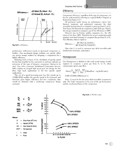
Compressor efficiency, regardless of the type of compressor, can
best be understood by referring to a typical Mollier Diagram as
depicted in Figure 3.2.7.
All produced heads shown on performance curves (iso-
thermal, isentropic and polytropic) represent the ideal
reversible head produced to compress a given gas from P 1 to P 2 .
This then is the theoretical compression path of the gas. That is,
the energy required to compress a gas if the efficiency is 100%.
However due to friction, sudden expansion etc., the effi-
ciency is less than 100%. Therefore the actual compression path
requires more head (energy) to compress the gas from P 1 to P 2 .
The efficiency then is equal to:
DE Ideal ðE 2 Ideal-E 1 Þ
Efficiency ¼
Fig 3.2.7 Efficiency DE Actual ðE 2 Actual-E 1 Þ
Note that () is used to represent any ideal reversible path
performance (efficiency) results in decreased compressor re- (isothermal, isentropic, polytropic).
liability. One mechanical design problem can quickly offset
any power savings realized by designing a compressor for a
higher efficiency. Horsepower
Referring back to Figure 3.2.6, calculation of specific speed
for the first impeller by the contractor or end user will give an Gas Horsepower is defined as the total actual energy (work)
indication of the type of dynamic compressor blading to be required to compress a given gas from P 1 to P 2 when
used. One other comment; Sundstrand Corporation success- compressing a given mass flow:
fully employs an integral high speed gear box design for low
flow, high head applications or for low specific speed HeadðÞ m kgf ft lbf ðMassFlow kg=hrðlb=minÞÞ
applications. kgm lbm
The use of a speed increasing gear box (for speeds up to 3,600 (33,000) (Efficiency) ()
34,000 RPM) enables the specific speed to be increased, and
therefore gives higher efficiency and less complexity than Note: () must be for the same ideal reversible compression
would be obtained with a multistage compressor design path. The brake horsepower is the sum of the gas horsepower
approach. and the mechanical losses of the compressor.
Fig 3.2.8 The Fan Laws
109