Page 133 - Subyek Teknik Mesin - Forsthoffers Best Practice Handbook for Rotating Machinery by William E Forsthoffer
P. 133

Compressor Best Practices    Be st Practice 3.2

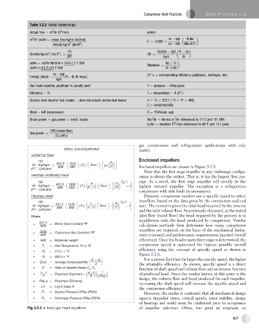
               Table 3.2.2 Useful relationships
                              3
                          3
               Actual flow e m /hr (ft /min)                            where:
                3
               m /hr (acfm) ¼ mass flow kg/hr (lbs/min)                 C ¼ 3;600 ¼  m   kgf     ft-lbs
                                       3
                                  3
                          density kg/m (lbs/ft )                                 hr   kW  Min-H:P:
                                                                           HEADm   kgf ft   lbs

                        3    3   ðPÞ
               Density kg=m ðlbs=t Þ¼                                  HD ¼
                                 ZRT                                          kgm      lb
               acfm ¼ m3/hr Nm3/hr x (101) (T) P 289                           kg     lb
                                                                       Massflow ¼
               (scfm x (14.7) (T)) P 520                                       hr  min
                          m   kgf                                      Eff’ y ¼ corresponding efficiency (polytropic, isentropic, etc)
               Energy ðidealÞ   ðft   lb=lb massÞ
                           kgm
               Use head equation, polytropic is usually used           P ¼ pressure e kPaa (psia)
                                                                                      )
               Efficiency e %                                           T ¼ temperature e K(R )
                                                                                  )
               Derived from impeller test results e does not include mechanical losses  K ¼ C þ 273.1 ( R ¼ F þ 460)


                                                                       Z ¼ compressibility
               Work e kW (horsepower)                                  R ¼ 1545/mol. wgt
                                                                                    3
                                                                         3
               Brake power ¼ gas power þ mech. losses                  Nm /hr ¼ Normal m /hr referenced to 17 C and 101 kPA

                                                                                    3
                                                                       (scfm ¼ standard FT /min referenced to 60 F and 14.7 psia)

                         ðHDÞðmass flowÞ
               Gas power ¼
                           ðCÞðeff’yÞ
                                                                   gas compressors and refrigeration applications with side
                               IDEAL GAS EQUATIONS                 loads).
                Isothermal Head
                   HD                                              Enclosed impellers
                M − Kgf/kgm =  847.4  1545  (T 1 )  ZAVG  LN  P 2
                (FT − Lbf/Lbm)  MW  MW               P 1           Enclosed impellers are shown in Figure 3.2.5.
                                                                     Note that the first stage impeller in any multistage configu-
                Isentropic (Adiabatic) Head
                                                                   ration is always the widest. That is, it has the largest flow pas-
                   HD                                      K − 1   sage. As a result, the first stage impeller will usually be the
                           847.4  1545      K           P 2  K
                M − Kgf/kgm =          (T 1 )  K − 1  ZAVG   − 1   highest stressed impeller. The exception is a refrigeration
                (FT − Lbf/Lbm)  MW  MW                  P 1
                                                                   compressor with side loads (economizers).
                Polytropic Head                                      Dynamic compressor vendors use a specific speed to select
                   HD                       n             n − 1    impellers, based on the data given by the contractors and end
                                                           n
                M - Kgf/kgm =  847.4  1545  (T 1 )  ZAVG  P 2   − 1  user. The vendor is given the total head required by the process
                            MW   MW        n −1        P 1
                (FT - Lbf/Lbm)                                     and the inlet volume flow. As previously discussed, at the stated
                Where:                                             inlet flow (rated flow) the head required by the process is in
                                                                   equilibrium with the head produced by compressor. Vendor
                    847.4  =  Metric Gas Constant “R”
                    MW                                             calculation methods then determine how many compressor
                                                                   impellers are required, on the basis of the mechanical limita-
                    1545  =  Customory Gas Constant “R”
                    MW                                             tions (stresses) and performance requirements (quoted overall
                    MW   =  Molecular weight                       efficiency). Once the head required per stage is determined, the
                         =  Inlet Temperature °K or °R             compressor speed is optimized for highest possible overall
                     T 1
                                                                   efficiency using the concept of specificspeed asshownin
                     °K  =  273.1 + °C
                                                                   Figure 3.2.6.
                     °R  =  460.0 + °F
                                                                     It is a proven fact that the larger the specific speed, the higher
                                            Z 1  + Z 2
                    ZAVG  =  Average Compressibility
                                              2                    the attainable efficiency. As shown, specific speed is a direct
                     K   =  Ratio of Specific Heats C p  / C v     function of shaft speed and volume flow and an inverse function
                    n - 1  =  Polytropic Exponent =  K - 1  1      of produced head. Since the vendor knows, at this point in the
                     n                      K  h Poly
                                                                   design, the volume flow and head produced for each impeller,
                    Poly h =  Polytropic Efficiency
                                                                   increasing the shaft speed will increase the specific speed and
                     Ln  =  Log to base A
                                                                   the compressor efficiency.
                         =  Suction Pressure KPaa (PSIA)
                                                                     However, the reader is cautioned that all mechanical design
                     P 1
                         =  Dischrage Pressure KPaa (PSIA)         aspects (impeller stress, critical speeds, rotor stability, design
                     P 2
                                                                   of bearings and seals) must be confirmed prior to acceptance
              Fig 3.2.3   Ideal gas head equations                 of impeller selection. Often, too great an emphasis on
                                                                                                               107
   128   129   130   131   132   133   134   135   136   137   138