
Page 138 - Subyek Teknik Mesin - Forsthoffers Best Practice Handbook for Rotating Machinery by William E Forsthoffer
P. 138
Be st Practice 3 .3 Compressor Best Practices
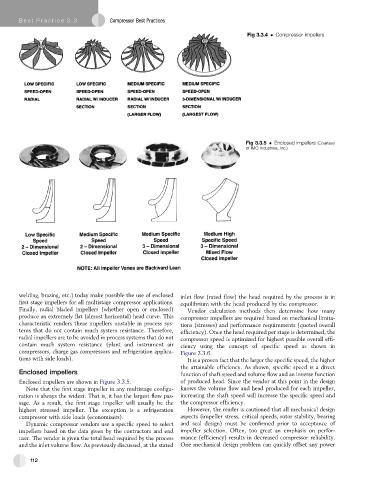
Fig 3.3.4 Compressor impellers
Fig 3.3.5 Enclosed impellers (Courtesy
of IMO Industries, Inc.)
welding, brazing, etc.) today make possible the use of enclosed inlet flow (rated flow) the head required by the process is in
first stage impellers for all multistage compressor applications. equilibrium with the head produced by the compressor.
Finally, radial bladed impellers (whether open or enclosed) Vendor calculation methods then determine how many
produce an extremely flat (almost horizontal) head curve. This compressor impellers are required based on mechanical limita-
characteristic renders these impellers unstable in process sys- tions (stresses) and performance requirements (quoted overall
tems that do not contain much system resistance. Therefore, efficiency). Once the head required per stage is determined, the
radial impellers are to be avoided in process systems that do not compressor speed is optimized for highest possible overall effi-
contain much system resistance (plant and instrument air ciency using the concept of specific speed as shown in
compressors, charge gas compressors and refrigeration applica- Figure 3.3.6.
tions with side loads). It is a proven fact that the larger the specific speed, the higher
the attainable efficiency. As shown, specific speed is a direct
Enclosed impellers function of shaft speed and volume flow and an inverse function
Enclosed impellers are shown in Figure 3.3.5. of produced head. Since the vendor at this point in the design
Note that the first stage impeller in any multistage configu- knows the volume flow and head produced for each impeller,
ration is always the widest. That is, it has the largest flow pas- increasing the shaft speed will increase the specific speed and
sage. As a result, the first stage impeller will usually be the the compressor efficiency.
highest stressed impeller. The exception is a refrigeration However, the reader is cautioned that all mechanical design
compressor with side loads (economizers). aspects (impeller stress, critical speeds, rotor stability, bearing
Dynamic compressor vendors use a specific speed to select and seal design) must be confirmed prior to acceptance of
impellers based on the data given by the contractors and end impeller selection. Often, too great an emphasis on perfor-
user. The vendor is given the total head required by the process mance (efficiency) results in decreased compressor reliability.
and the inlet volume flow. As previously discussed, at the stated One mechanical design problem can quickly offset any power
112