
Page 140 - Subyek Teknik Mesin - Forsthoffers Best Practice Handbook for Rotating Machinery by William E Forsthoffer
P. 140
Be st Practice 3 .3 Compressor Best Practices
Every turbo-compressor must have its rotor system’s critical - Maximum speed 6,600 rpm
speeds determined prior to manufacture. In this section, we will - Minimum speed 4,000 rpm
follow the procedure for the determination of the necessary
Remember, changing of any value of support stiffness will
parameters to define a rotor system’s critical speed. The pro-
cedure is commonly known as determination of rotor response. change the critical speed. Support stiffness in lbs/inch is plotted
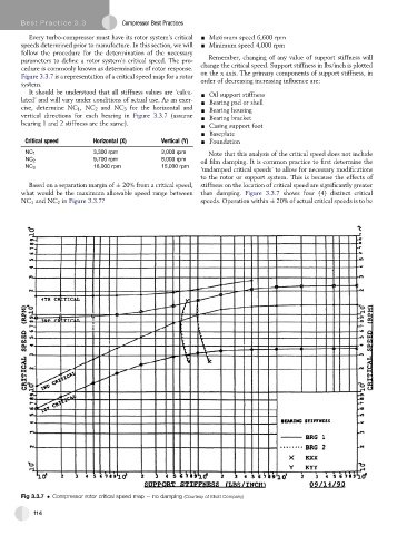
Figure 3.3.7 is a representation of a critical speed map for a rotor on the x axis. The primary components of support stiffness, in
system. order of decreasing increasing influence are:
It should be understood that all stiffness values are ‘calcu- - Oil support stiffness
lated’ and will vary under conditions of actual use. As an exer- - Bearing pad or shell
cise, determine NC 1 ,NC 2 and NC 3 for the horizontal and - Bearing housing
vertical directions for each bearing in Figure 3.3.7 (assume - Bearing bracket
bearing 1 and 2 stiffness are the same). - Casing support foot
- Baseplate
Critical speed Horizontal (X) Vertical (Y) - Foundation
NC 1 3,300 rpm 3,000 rpm Note that this analysis of the critical speed does not include
oil film damping. It is common practice to first determine the
NC 2 9,700 rpm 8,000 rpm
NC 3 16,000 rpm 15,000 rpm
‘undamped critical speeds’ to allow for necessary modifications
to the rotor or support system. This is because the effects of
Based on a separation margin of 20% from a critical speed, stiffness on the location of critical speed are significantly greater
what would be the maximum allowable speed range between than damping. Figure 3.3.7 shows four (4) distinct critical
NC 1 and NC 2 in Figure 3.3.7? speeds. Operation within 20% of actual critical speeds is to be
Fig 3.3.7 Compressor rotor critical speed map e no damping (Courtesy of Elliott Company)
114