
Page 156 - T. Anderson-Fracture Mechanics - Fundamentals and Applns.-CRC (2005)
P. 156
1656_C003.fm Page 136 Monday, May 23, 2005 5:42 PM
136 Fracture Mechanics: Fundamentals and Applications
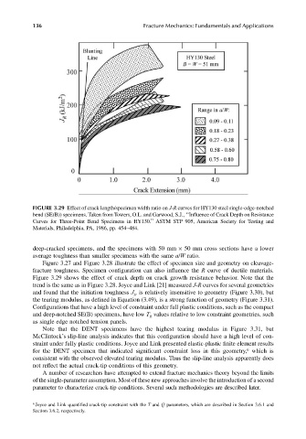
FIGURE 3.29 Effect of crack length/specimen width ratio on J-R curves for HY130 steel single-edge-notched
bend (SE(B)) specimens. Taken from Towers, O.L. and Garwood, S.J., ‘‘Influence of Crack Depth on Resistance
Curves for Three-Point Bend Specimens in HY130.’’ ASTM STP 905, American Society for Testing and
Materials, Philadelphia, PA, 1986, pp. 454–484.
deep-cracked specimens, and the specimens with 50 mm × 50 mm cross sections have a lower
average toughness than smaller specimens with the same a/W ratio.
Figure 3.27 and Figure 3.28 illustrate the effect of specimen size and geometry on cleavage-
fracture toughness. Specimen configuration can also influence the R curve of ductile materials.
Figure 3.29 shows the effect of crack depth on crack growth resistance behavior. Note that the
trend is the same as in Figure 3.28. Joyce and Link [21] measured J-R curves for several geometries
and found that the initiation toughness J is relatively insensitive to geometry (Figure 3.30), but
Ic
the tearing modulus, as defined in Equation (3.49), is a strong function of geometry (Figure 3.31).
Configurations that have a high level of constraint under full plastic conditions, such as the compact
and deep-notched SE(B) specimens, have low T values relative to low constraint geometries, such
R
as single edge notched tension panels.
Note that the DENT specimens have the highest tearing modulus in Figure 3.31, but
McClintock’s slip-line analysis indicates that this configuration should have a high level of con-
straint under fully plastic conditions. Joyce and Link presented elastic-plastic finite element results
6
for the DENT specimen that indicated significant constraint loss in this geometry, which is
consistent with the observed elevated tearing modulus. Thus the slip-line analysis apparently does
not reflect the actual crack-tip conditions of this geometry.
A number of researchers have attempted to extend fracture mechanics theory beyond the limits
of the single-parameter assumption. Most of these new approaches involve the introduction of a second
parameter to characterize crack-tip conditions. Several such methodologies are described later.
6 Joyce and Link quantified crack-tip constraint with the T and Q parameters, which are described in Section 3.6.1 and
Section 3.6.2, respectively.