
Page 161 - T. Anderson-Fracture Mechanics - Fundamentals and Applns.-CRC (2005)
P. 161
1656_C003.fm Page 141 Monday, May 23, 2005 5:42 PM
Elastic-Plastic Fracture Mechanics 141
they noted that
π
)
( σ yy Diff ≈ ( σ xx Diff > > ( σ xy Diff for ||θ ≤
)
)
2
Thus the difference field corresponds approximately to a uniform hydrostatic shift of the stress
field in front of the crack tip. O’Dowd and Shih designated the amplitude of this approximate
difference field by the letter Q. Equation (3.68b) then becomes
σ ij σ ≈ ij T=0 σ+( o ij | | ≤ π (3.69)
δQ
θ
)
2
where d is the Kronecker delta. The Q parameter can be inferred by subtracting the stress field
ij
for the T = 0 reference state from the stress field of interest. O’Dowd and Shih and most subsequent
researchers defined Q as follows:
σ − σ ( ) rσ
Q ≡ yy yy T=0 at q = 0 and o = 2 (3.70)
σ o J
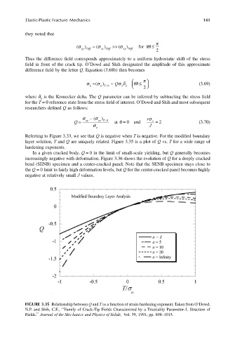
Referring to Figure 3.33, we see that Q is negative when T is negative. For the modified boundary
layer solution, T and Q are uniquely related. Figure 3.35 is a plot of Q vs. T for a wide range of
hardening exponents.
In a given cracked body, Q = 0 in the limit of small-scale yielding, but Q generally becomes
increasingly negative with deformation. Figure 3.36 shows the evolution of Q for a deeply cracked
bend (SENB) specimen and a center-cracked panel. Note that the SENB specimen stays close to
the Q = 0 limit to fairly high deformation levels, but Q for the center-cracked panel becomes highly
negative at relatively small J values.
FIGURE 3.35 Relationship between Q and T as a function of strain-hardening exponent. Taken from O’Dowd,
N.P. and Shih, C.F., ‘‘Family of Crack-Tip Fields Characterized by a Triaxiality Parameter–I. Structure of
Fields.’’ Journal of the Mechanics and Physics of Solids, Vol. 39, 1991, pp. 898–1015.