
Page 160 - T. Anderson-Fracture Mechanics - Fundamentals and Applns.-CRC (2005)
P. 160
1656_C003.fm Page 140 Monday, May 23, 2005 5:42 PM
140 Fracture Mechanics: Fundamentals and Applications
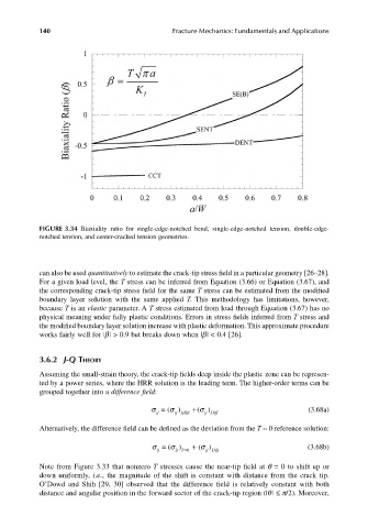
FIGURE 3.34 Biaxiality ratio for single-edge-notched bend, single-edge-notched tension, double-edge-
notched tension, and center-cracked tension geometries.
can also be used quantitatively to estimate the crack-tip stress field in a particular geometry [26–28].
For a given load level, the T stress can be inferred from Equation (3.66) or Equation (3.67), and
the corresponding crack-tip stress field for the same T stress can be estimated from the modified
boundary layer solution with the same applied T. This methodology has limitations, however,
because T is an elastic parameter. A T stress estimated from load through Equation (3.67) has no
physical meaning under fully plastic conditions. Errors in stress fields inferred from T stress and
the modified boundary layer solution increase with plastic deformation. This approximate procedure
works fairly well for |b | > 0.9 but breaks down when |b | < 0.4 [26].
3.6.2 J-Q THEORY
Assuming the small-strain theory, the crack-tip fields deep inside the plastic zone can be represen-
ted by a power series, where the HRR solution is the leading term. The higher-order terms can be
grouped together into a difference field:
σ ij σ = ij HRR ( σ + ( ij Diff (3.68a)
)
)
Alternatively, the difference field can be defined as the deviation from the T = 0 reference solution:
σ ij σ = ij T=0 ( σ + ( ij Diff (3.68b)
)
)
Note from Figure 3.33 that nonzero T stresses cause the near-tip field at q = 0 to shift up or
down uniformly, i.e., the magnitude of the shift is constant with distance from the crack tip.
O’Dowd and Shih [29, 30] observed that the difference field is relatively constant with both
distance and angular position in the forward sector of the crack-tip region (|q | ≤ p/2). Moreover,