
Page 362 - T. Anderson-Fracture Mechanics - Fundamentals and Applns.-CRC (2005)
P. 362
1656_C007.fm Page 342 Monday, May 23, 2005 5:54 PM
342 Fracture Mechanics: Fundamentals and Applications
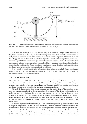
FIGURE 7.41 A pendulum device for impact testing. The energy absorbed by the specimen is equal to the
weight of the crosshead, times the difference in height before and after impact.
A number of investigators [46–52] have attempted to correlate Charpy energy to fracture
toughness parameters such as K . Some of these empirical correlations seem to work reasonably
Ic
well, but most correlations are often unreliable. There are several important differences between
the Charpy test and fracture mechanics tests that preclude simple relationships between the qual-
itative and quantitative measures of toughness. The Charpy test contains a blunt notch, while fracture
mechanics specimens have sharp fatigue cracks. The Charpy specimen is subsize, and thus has low
constraint. In addition, the Charpy specimen experiences impact loading, while most fracture
toughness tests are conducted under quasistatic conditions.
It is possible to obtain quantitative information from fatigue precracked Charpy specimens,
provided the tup (i.e., the striker) is instrumented [53,54]. Such an experiment is essentially a
miniature dynamic fracture toughness test.
7.9.2 DROP WEIGHT TEST
The ASTM standard E 208 [43] outlines the procedure for performing the Pellini drop weight test.
A plate specimen with a starter notch in a brittle weld bead is impacted in three-point bending. A
cleavage crack initiates in the weld bead and runs into the parent metal. If the material is sufficiently
tough, the crack arrests, otherwise the specimen fractures completely.
Figure 7.42 illustrates the drop weight specimen and the testing fixture. The crosshead drops
onto the specimen, causing it to deflect a predetermined amount. The fixture is designed with a
deflection stop, which limits the displacement in the specimen. A crack initiates at the starter notch
and either propagates or arrests, depending on the temperature and material properties. A ‘‘break’’
result is recorded when the running crack reaches at least one specimen edge. A ‘‘no-break’’ result
is recorded if the crack arrests in the parent metal. Figure 7.43 gives examples of break and no-
break results.
A nil-ductility transition temperature (NDTT) is obtained by performing drop weight tests over
a range of temperatures, in 5°C or 10°F increments. When a no-break result is recorded, the
temperature is decreased for the next test; the test temperature is increased when a specimen fails.
When break and no-break results are obtained at adjoining temperatures, a second test is performed
at the no-break temperature. If this specimen fails, a test is performed at one temperature increment
(5°C or 10°F) higher. The process is repeated until two no-break results are obtained at one