
Page 62 - T. Anderson-Fracture Mechanics - Fundamentals and Applns.-CRC (2005)
P. 62
1656_C02.fm Page 42 Thursday, April 14, 2005 6:28 PM
42 Fracture Mechanics: Fundamentals and Applications
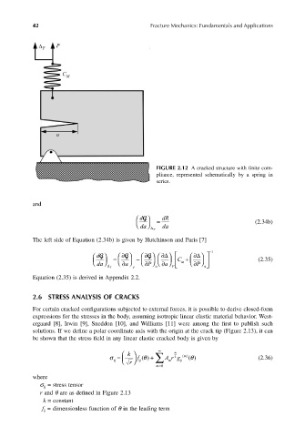
FIGURE 2.12 A cracked structure with finite com-
pliance, represented schematically by a spring in
series.
and
dG = dR
da ∆ T da (2.34b)
The left side of Equation (2.34b) is given by Hutchinson and Paris [7]
dG = ∂ G − ∂ G ∂∆ C + ∂∆ −1
da ∆ T a ∂ P ∂ P a ∂ m ∂ P (2.35)
a
P
a
Equation (2.35) is derived in Appendix 2.2.
2.6 STRESS ANALYSIS OF CRACKS
For certain cracked configurations subjected to external forces, it is possible to derive closed-form
expressions for the stresses in the body, assuming isotropic linear elastic material behavior. West-
ergaard [8], Irwin [9], Sneddon [10], and Williams [11] were among the first to publish such
solutions. If we define a polar coordinate axis with the origin at the crack tip (Figure 2.13), it can
be shown that the stress field in any linear elastic cracked body is given by
∞
m
σ ij k f ij θ = ∑ m r + m 2 g ij () () (2.36)
θ A ()
r
m=0
where
σ = stress tensor
ij
r and θ are as defined in Figure 2.13
k = constant
f = dimensionless function of θ in the leading term
ij