
Page 63 - T. Anderson-Fracture Mechanics - Fundamentals and Applns.-CRC (2005)
P. 63
1656_C02.fm Page 43 Thursday, April 14, 2005 6:28 PM
Linear Elastic Fracture Mechanics 43
FIGURE 2.13 Definition of the coordinate axis
ahead of a crack tip. The z direction is normal to
the page.
m
For the higher-order terms, A is the amplitude and g m() is a dimensionless function of θ for
ij
the mth term. The higher-order terms depend on geometry, but the solution for any given config-
uration contains a leading term that is proportional to 1 r .As r → 0, the leading term approaches
infinity, but the other terms remain finite or approach zero. Thus, stress near the crack tip varies
with 1 r , regardless of the configuration of the cracked body. It can also be shown that displace-
ment near the crack tip varies with r . Equation (2.36) describes a stress singularity, since stress
is asymptotic to r = 0. The basis of this relationship is explored in more detail in Appendix 2.3.
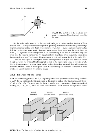
There are three types of loading that a crack can experience, as Figure 2.14 illustrates. Mode
I loading, where the principal load is applied normal to the crack plane, tends to open the crack.
Mode II corresponds to in-plane shear loading and tends to slide one crack face with respect to
the other. Mode III refers to out-of-plane shear. A cracked body can be loaded in any one of these
modes, or a combination of two or three modes.
2.6.1 THE STRESS INTENSITY FACTOR
Each mode of loading produces the 1 r singularity at the crack tip, but the proportionality constants
k and f depend on the mode. It is convenient at this point to replace k by the stress intensity factor
ij
=
K, where Kk 2π . The stress intensity factor is usually given a subscript to denote the mode of
loading, i.e., K , K , or K . Thus, the stress fields ahead of a crack tip in an isotropic linear elastic
II
III
I
FIGURE 2.14 The three modes of loading that can be applied to a crack.