
Page 65 - T. Anderson-Fracture Mechanics - Fundamentals and Applns.-CRC (2005)
P. 65
1656_C02.fm Page 45 Thursday, April 14, 2005 6:28 PM
Linear Elastic Fracture Mechanics 45
TABLE 2.3
Nonzero Stress and Displacement Components in Mode III
(Linear Elastic, Isotropic Material)
K θ
τ xz =− III sin
2
2 πr
K θ
τ yz = III cos
2
2 πr
θ
u = 2 K µ III 2π r sin
z
2
Consider the Mode I singular field on the crack plane, where θ = 0. According to Table 2.1,
the stresses in the x and y direction are equal:
K
σ σ = = I (2.39)
xx
yy
2 πr
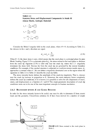
When θ = 0, the shear stress is zero, which means that the crack plane is a principal plane for pure
Mode I loading. Figure 2.15 is a schematic plot of σ , the stress normal to the crack plane vs. distance
yy
from the crack tip. Equation (2.39) is valid only near the crack tip, where the 1 r singularity
dominates the stress field. Stresses far from the crack tip are governed by the remote boundary
conditions. For example, if the cracked structure is subjected to a uniform remote tensile stress, σ yy
∞
approaches a constant value σ . We can define a singularity-dominated zone as the region where the
equations in Table 2.1 to Table 2.3 describe the crack-tip fields.
The stress intensity factor defines the amplitude of the crack-tip singularity. That is, stresses
near the crack tip increase in proportion to K. Moreover, the stress intensity factor completely
defines the crack tip conditions; if K is known, it is possible to solve for all components of stress,
strain, and displacement as a function of r and θ. This single-parameter description of crack tip
conditions turns out to be one of the most important concepts in fracture mechanics.
2.6.2 RELATIONSHIP BETWEEN K AND GLOBAL BEHAVIOR
In order for the stress intensity factor to be useful, one must be able to determine K from remote
loads and the geometry. Closed-form solutions for K have been derived for a number of simple
FIGURE 2.15 Stress normal to the crack plane in
Mode I.