Page 64 - T. Anderson-Fracture Mechanics - Fundamentals and Applns.-CRC (2005)
P. 64

1656_C02.fm  Page 44  Thursday, April 14, 2005  6:28 PM


                       44                                    Fracture Mechanics: Fundamentals and Applications
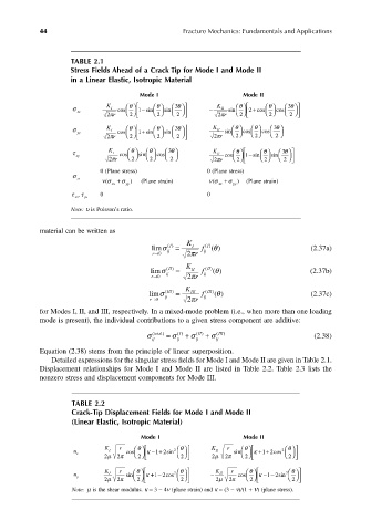


                               TABLE 2.1
                               Stress Fields Ahead of a Crack Tip for Mode I and Mode II
                               in a Linear Elastic, Isotropic Material

                                                  Mode I                      Mode II
                                                                                     θ
                                                                             θ
                                                            θ 
                               σ         K I  cos  θ  1 sin−  θ    sin  3    −  K II  sin    2  + cos    cos  3θ   
                                 xx             2      2     2                  
                                         2π r                        2π r  2      2    2  
                                                                                       θ 
                                                            θ 
                               σ yy      K I  cos  θ  1 sin+  θ    sin   3       K II  sin  θ  cos  θ   cos  3 
                                         2π r    2       2     2     2π r    2    2     2 
                                                          θ 
                                                                                         θ 
                               τ xy       K I  cos   θ  sin  θ   cos   3   K II  cos  θ  1 sin−  θ    sin  3  
                                         2π r    2     2     2   2π r    2       2     2   
                                       0 (Plane stress)             0 (Plane stress)
                               σ zz    νσ xx  +  σ )  (Plane strain)  νσ xx  +  σ )  (Plane strain)
                                        (
                                                                     (
                                              yy
                                                                           yy
                               τ  , τ  0                            0
                                xz  yz
                               Note: υ is Poisson’s ratio.
                       material can be written as
                                                              K
                                                                      θ
                                                     limσ () I  =  I  f  () I  ( )              (2.37a)
                                                     r→0  ij   2π r  ij
                                                              K
                                                     limσ ()  =  II  f  () ( )                  (2.37b)
                                                                    II
                                                                      θ
                                                          II
                                                     r→0  ij   2π r  ij
                                                              K
                                                                      θ
                                                    limσ (III )  =  III  f  (III  ) ( )         (2.37c)
                                                    r→0  ij    2π r  ij
                       for Modes I, II, and III, respectively. In a mixed-mode problem (i.e., when more than one loading
                       mode is present), the individual contributions to a given stress component are additive:
                                                    σ  ij (total  )  σ  ij I ( )  σ =  ij (  II)  +  σ +  ( ij III)  (2.38)
                       Equation (2.38) stems from the principle of linear superposition.
                          Detailed expressions for the singular stress fields for Mode I and Mode II are given in Table 2.1.
                       Displacement relationships for Mode I and Mode II are listed in Table 2.2. Table 2.3 lists the
                       nonzero stress and displacement components for Mode III.


                               TABLE 2.2
                               Crack-Tip Displacement Fields for Mode I and Mode II
                               (Linear Elastic, Isotropic Material)

                                                  Mode I                      Mode II
                                                                                         
                                                            
                                u       K I  r  cos   θ   κ −+  2 θ    K II  r  sin  θ   κ ++  2 θ  
                                                      12sin
                                                                                   12cos
                                 x                2        2             2        2  
                                        2 µ  2 π                   2 µ  2 π              
                                                                               θ
                                                                                            
                                                            
                                u       K I  r  sin  θ   κ +−  2 θ    −  K II  r  cos    κ −−  2 θ
                                                      12cos
                                                                                    12sin
                                 y                                                   
                                        2 µ  2 π  2        2      2 µ  2 π  2         2  
                               Note: µ is the shear modulus. κ = 3 − 4ν (plane strain) and κ = (3 − ν)/(1 + ν) (plane stress).
   59   60   61   62   63   64   65   66   67   68   69