
Page 126 - Fundamentals of Communications Systems
P. 126
4.2 Chapter Four
TABLE 4.1 Carrier frequency assignments for different methods
of information transmission
Type of Transmission Center Frequency of Transmission
Telephone Modems 1600–1800 Hz
AM radio 530–1600 kHz
CB radio 27 MHz
FM radio 88–108 MHz
VHF TV 178–216 MHz
Cellular radio 850 MHz, 1.8 GHz
Indoor Wireless Networks 2.4 GHz
Commercial Satellite Downlink 3.7–4.2 GHz
Commercial Satellite Uplink 5.9–6.4 GHz
Fiber Optics 2 × 10 14 Hz
4.2 Baseband Representation of Bandpass Signals
The first step in the development of a complex baseband representation is to
define a bandpass signal.
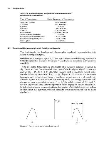
Definition 4.1 A bandpass signal, x c (t), is a signal whose one-sided energy spectrum is
both: (1) centered at a nonzero frequency, f C , and (2) does not extend in frequency to
zero (DC).
The two-sided transmission bandwidth of a signal is typically denoted by
B T Hertz so that the one-sided spectrum of the bandpass signal is zero ex-
cept in [ f C − B T /2, f C + B T /2]. This implies that a bandpass signal satis-
fies the following constraint: B T /2 < f C . Figure 4.1 illustrates a conformant
bandpass energy spectrum. Since a bandpass signal, x c (t), is a physically re-
alizable signal it is real valued and consequently the energy spectrum will
always be even symmetric around f = 0. The relative sizes of B T and f C
are not important, only that the spectrum takes negligible values around DC.
In telephone modem communications this region of negligible spectral values
is only about 300 Hz wide, while in satellite communications it can be many
gigahertz.
G (f )
x
c
B T
f
−f f
C C
Figure 4.1 Energy spectrum of a bandpass signal.