
Page 139 - Fundamentals of Communications Systems
P. 139
Complex Baseband Representation of Bandpass Signals 4.15
H ( f )
c
H( f )
A
A
B
T
f f
−f c f c −f c f c
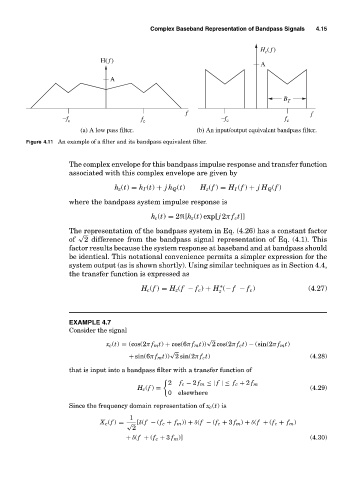
(a) A low pass filter. (b) An input/output equivalent bandpass filter.
Figure 4.11 An example of a filter and its bandpass equivalent filter.
The complex envelope for this bandpass impulse response and transfer function
associated with this complex envelope are given by
h z (t) = h I (t) + jh Q (t) H z (f ) = H I (f ) + jH Q (f )
where the bandpass system impulse response is
h c (t) = 2
[h z (t) exp[ j 2π f c t]]
The representation of the bandpass system in Eq. (4.26) has a constant factor
√
of 2 difference from the bandpass signal representation of Eq. (4.1). This
factor results because the system response at baseband and at bandpass should
be identical. This notational convenience permits a simpler expression for the
system output (as is shown shortly). Using similar techniques as in Section 4.4,
the transfer function is expressed as
∗
H c (f ) = H z (f − f c ) + H (− f − f c ) (4.27)
z
EXAMPLE 4.7
Consider the signal
√
x c (t) = (cos(2π f m t) + cos(6π f m t)) 2 cos(2π f c t) − (sin(2π f m t)
√
+ sin(6π f m t)) 2 sin(2π f c t) (4.28)
that is input into a bandpass filter with a transfer function of
2 f c − 2 f m ≤| f |≤ f c + 2 f m
H c (f ) = (4.29)
0 elsewhere
Since the frequency domain representation of x c (t)is
1
X c (f ) = √ [δ(f − (f c + f m )) + δ(f − (f c + 3 f m ) + δ(f + (f c + f m )
2
+ δ(f + (f c + 3 f m )] (4.30)