
Page 142 - Fundamentals of Communications Systems
P. 142
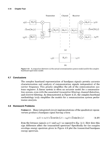
4.18  Chapter Four


                                              Transmitter   Channel   Receiver

                        x (t)x t()  H (f)                                         H (f )  y (t)
                                  1
                                                                                   5
                                                                                          I
                         I I
                             cos π f t)                                               cos π f t)
                            2  (2  c             ∑   H (f)   H (f )   H (f)          2   (2  c
                                                              3
                                                      2
                                          π                            4     π
                                           2                                   2
                        x (t)x t()  H (f)                                         H (f )  y (t)
                                                                                           Q
                                 1
                         QQ
                                                                                   5
                                                               (a)


                                                  z(t)t()    H (f )      y (t)
                                                  x
                                                               z
                                                                          z
                                                   z
                                                               (b)
                       Figure 4.13 A comparison between (a) the actual communication system model and (b) the complex
                       baseband equivalent model.


           4.7 Conclusions
                       The complex baseband representation of bandpass signals permits accurate
                       characterization and analysis of communication signals independent of the
                       carrier frequency. This greatly simplifies the job of the communication sys-
                       tems engineer. A linear system is often an accurate model for a communica-
                       tion system, even with the associated transmitter filtering, channel distortion,
                       and receiver filtering. As demonstrated in Figure 4.13, the complex baseband
                       methodology truly simplifies the models for a communication system perfor-
                       mance analysis.


           4.8 Homework Problems
                       Problem 4.1. Many integrated circuit implementations of the quadrature upcon-
                       verters produce a bandpass signal having a form
                                                 √                  √
                                      x c (t) = x I (t) 2 cos(2π f c t) + x Q (t) 2 sin(2π f c t)  (4.40)
                       from the lowpass signals x I (t) and x Q (t) as opposed to Eq. (4.1). How does this
                       sign difference affect the transmitted spectrum? Specifically for the complex
                       envelope energy spectrum given in Figure 4.9 plot the transmitted bandpass
                       energy spectrum.