
Page 145 - Fundamentals of Communications Systems
P. 145
Complex Baseband Representation of Bandpass Signals 4.21
(
2 cos 2πf t) 2 cos 2πf t)
(
c
c
π 2 2 cos 2πf t( −π 2) = 2 sin 2πf t( )
c c
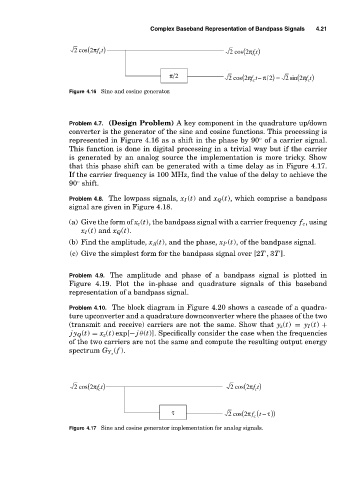
Figure 4.16 Sine and cosine generator.
Problem 4.7. (Design Problem) A key component in the quadrature up/down
converter is the generator of the sine and cosine functions. This processing is
represented in Figure 4.16 as a shift in the phase by 90 of a carrier signal.
◦
This function is done in digital processing in a trivial way but if the carrier
is generated by an analog source the implementation is more tricky. Show
that this phase shift can be generated with a time delay as in Figure 4.17.
If the carrier frequency is 100 MHz, find the value of the delay to achieve the
90 shift.
◦
Problem 4.8. The lowpass signals, x I (t) and x Q (t), which comprise a bandpass
signal are given in Figure 4.18.
(a) Give the form of x c (t), the bandpass signal with a carrier frequency f c , using
x I (t) and x Q (t).
(b) Find the amplitude, x A(t), and the phase, x P (t), of the bandpass signal.
(c) Give the simplest form for the bandpass signal over [2T ,3T ].
Problem 4.9. The amplitude and phase of a bandpass signal is plotted in
Figure 4.19. Plot the in-phase and quadrature signals of this baseband
representation of a bandpass signal.
Problem 4.10. The block diagram in Figure 4.20 shows a cascade of a quadra-
ture upconverter and a quadrature downconverter where the phases of the two
(transmit and receive) carriers are not the same. Show that y z (t) = y I (t) +
jy Q (t) = x z (t) exp[− j θ(t)]. Specifically consider the case when the frequencies
of the two carriers are not the same and compute the resulting output energy
(f ).
spectrum G Y z
(
2 cos 2πf t) 2 cos 2πf t)
(
c c
τ 2 cos 2πf t( c ( −τ))
Figure 4.17 Sine and cosine generator implementation for analog signals.