
Page 149 - Fundamentals of Communications Systems
P. 149
Complex Baseband Representation of Bandpass Signals 4.25
[
exp j2πf t] h t() y t()
0
z
z
[
(
τ d exp j2πf t−τ )]
0
d
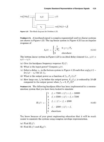
Figure 4.23 The block diagram for Problem 4.15.
Problem 4.15. A baseband signal (a complex exponential) and two linear systems
are shown in Figure 4.23. The top linear system in Figure 4.23 has an impulse
response of
⎪ 1
⎧
0 ≤ t ≤ T p
⎨
h z (t) = T p (4.44)
⎪
0 elsewhere
⎩
The bottom linear system in Figure 4.23 is an ideal delay element (i.e., y z (t) =
x z (t − τ d )).
(a) Give the bandpass frequency response H c (f ).
(b) What is the input power? Compute y z (t).
(c) Select a delay, τ d , in the bottom system in Figure 4.23 such that arg[y z (t)] =
2π f 0 (t − τ d ) for all f 0 .
(f 0 )?
(d) What is the output power as a function of f 0 , P y z
(f 0 ), is reduced by 10 dB
(e) How large can f 0 be before the output power, P y z
(0)?
compared to the output power when f 0 = 0, P y z
Problem 4.16. The following bandpass filter has been implemented in a commu-
nication system that you have been tasked to simulate
⎧
⎪1 f c + 7500 ≤| f |≤ f c + 10000
⎪
⎪
⎪2 f c + 2500 ≤| f | < f c + 7500
⎪
⎪
⎪
⎪
⎪4
⎪
⎪
f c ≤| f | < f c + 2500
⎨
H c (f ) = 3 (4.45)
⎪3
⎪
⎪
⎪
⎪ f c − 2500 ≤| f | < f c
⎪ 4
⎪
⎪
⎪
⎩0 elsewhere
⎪
⎪
You know because of your great engineering education that it will be much
easier to simulate the system using complex envelope representation.
(a) Find H z (f ).
(b) Find H I (f ) and H Q (f ).