
Page 147 - Fundamentals of Communications Systems
P. 147
Complex Baseband Representation of Bandpass Signals 4.23
Problem 4.11. A periodic real signal of bandwidth W and period T is x I (t) and
x Q (t) = 0 for a bandpass signal of carrier frequency f c > W.
(a) Can the resulting bandpass signal, x c (t), be periodic with a period of T c < T ?
If yes, give an example.
(b) Can the resulting bandpass signal, x c (t), be periodic with a period of T c > T ?
If yes, give an example.
(c) Can the resulting bandpass signal, x c (t), be periodic with a period of T c = T ?
If yes, give an example.
(d) Can the resulting bandpass signal, x c (t), be aperiodic? If yes, give an
example.
Problem 4.12. In communication systems bandpass signals are often processed
in digital processors. To accomplish the processing, the bandpass signal must
first be converted from an analog signal to a digital signal. For this problem
assume this is done by ideal sampling. Assume the sampling frequency, f s ,is
set at four times the carrier frequency.
(a) Under what conditions on the complex envelope will this sampling rate be
greater than the Nyquist sampling rate (see Section 2.4.1) for the bandpass
signal?
(b) Give the values for the bandpass signal samples for x c (0), x c ( 1 ), x c ( 2 ),
4 f c 4 f c
x c ( 3 ), and x c ( 4 ).
4 f c 4 f c
(c) By examining the results in (b) can you postulate a simple way to down-
convert the analog signal when f s = 4 f c and produce x I (t) and x Q (t)? This
simple idea is frequently used in engineering practice and is known as f s /4
downconversion.
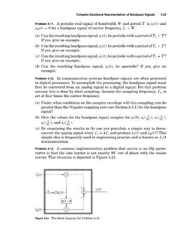
Problem 4.13. A common implementation problem that occurs in an I/Q upcon-
verter is that the sine carrier is not exactly 90 out of phase with the cosine
◦
carrier. This situation is depicted in Figure 4.21.
~
x t()
I
+ x t()
2 cos 2πf t( c ) ∑ c
−
π/2 + θ
~
x t()
Q
Figure 4.21 The block diagram for Problem 4.13.