
Page 165 - Fundamentals of Communications Systems
P. 165
Analog Communications Basics 5.5
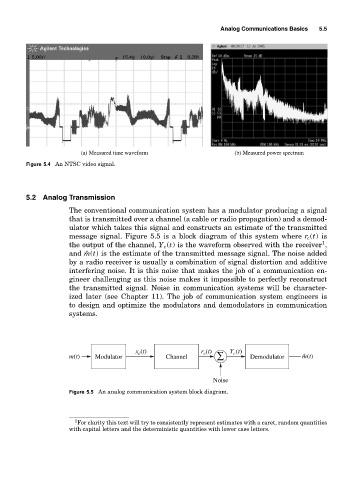
(a) Measured time waveform (b) Measured power spectrum
Figure 5.4 An NTSC video signal.
5.2 Analog Transmission
The conventional communication system has a modulator producing a signal
that is transmitted over a channel (a cable or radio propagation) and a demod-
ulator which takes this signal and constructs an estimate of the transmitted
message signal. Figure 5.5 is a block diagram of this system where r c (t)is
1
the output of the channel, Y c (t) is the waveform observed with the receiver ,
and ˆm(t) is the estimate of the transmitted message signal. The noise added
by a radio receiver is usually a combination of signal distortion and additive
interfering noise. It is this noise that makes the job of a communication en-
gineer challenging as this noise makes it impossible to perfectly reconstruct
the transmitted signal. Noise in communication systems will be character-
ized later (see Chapter 11). The job of communication system engineers is
to design and optimize the modulators and demodulators in communication
systems.
x (t) r (t) Y (t)
c
c
c
m(t) Modulator Channel ∑ Demodulator mˆ (t)
Noise
Figure 5.5 An analog communication system block diagram.
1 For clarity this text will try to consistently represent estimates with a caret, random quantities
with capital letters and the deterministic quantities with lower case letters.