
Page 168 - Fundamentals of Communications Systems
P. 168
5.8 Chapter Five
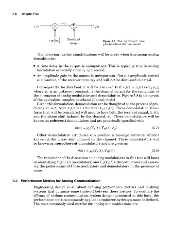
r (t)
z
x (t) ∑ Y (t)
z z
exp jφ [ p] Baseband Figure 5.8 The equivalent com-
Noise plex baseband channel model.
The following further simplifications will be made when discussing analog
demodulation
■ A time delay in the output is unimportant. This is typically true in analog
modulation especially since τ p 1 second.
■ An amplitude gain in the output is unimportant. Output amplitude control
is a function of the receiver circuitry and will not be discussed in detail.
Consequently, for this book it will be assumed that r z (t) = x z (t) exp[ j φ p ],
where φ p is an unknown constant, is the channel output for the remainder of
the discussion of analog modulation and demodulation. Figure 5.8 is a diagram
of the equivalent complex baseband channel model.
Given this formulation, demodulation can be thought of as the process of pro-
ducing an ˆm(t) from Y z (t) via a function d (Y z (t)). Some demodulation struc-
tures that will be considered will need to have both the received signal, Y z (t),
and the phase shift induced by the channel, φ p . These demodulators will be
known as coherent demodulators and are generically specified with
ˆ m(t) = g c (Y I (t), Y Q (t), φ p ) (5.7)
Other demodulation structures can produce a message estimate without
knowning the phase shift induced by the channel. These demodulators will
be known as noncoherent demodulators and are given as
ˆ m(t) = g n (Y I (t), Y Q (t)) (5.8)
The remainder of the discussion on analog modulations in this text will focus
on identifying m (m(t)) (modulators) and d (Y z (t)) (demodulators) and assess-
ing the performance of these modulators and demodulators in the presence of
noise.
5.3 Performance Metrics for Analog Communication
Engineering design is all about defining performance metrics and building
systems that optimize some trade-off between these metrics. To evaluate the
efficacy of various communication system designs presented in this book, the
performance metrics commonly applied in engineering design must be defined.
The most commonly used metrics for analog communications are