
Page 166 - Fundamentals of Communications Systems
P. 166
5.6 Chapter Five
x (t) Baseband to
z
•
m(t) Γ () Bandpass x (t)
c
m
Converter
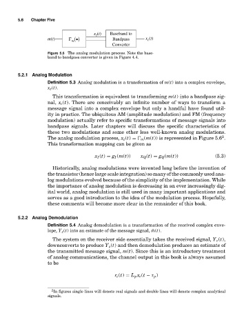
Figure 5.6 The analog modulation process. Note the base-
band to bandpass converter is given in Figure 4.4.
5.2.1 Analog Modulation
Definition 5.3 Analog modulation is a transformation of m(t) into a complex envelope,
x z (t).
This transformation is equivalent to transforming m(t) into a bandpass sig-
nal, x c (t). There are conceivably an infinite number of ways to transform a
message signal into a complex envelope but only a handful have found util-
ity in practice. The ubiquitous AM (amplitude modulation) and FM (frequency
modulation) actually refer to specific transformations of message signals into
bandpass signals. Later chapters will discuss the specific characteristics of
these two modulations and some other less well-known analog modulations.
2
The analog modulation process, x z (t) = m (m(t)) is represented in Figure 5.6 .
This transformation mapping can be given as
x I (t) = g I (m(t)) x Q (t) = g Q (m(t)) (5.3)
Historically, analog modulations were invented long before the invention of
the transistor (hence large scale integration) so many of the commonly used ana-
log modulations evolved because of the simplicity of the implementation. While
the importance of analog modulation is decreasing in an ever increasingly dig-
ital world, analog modulation is still used in many important applications and
serves as a good introduction to the idea of the modulation process. Hopefully,
these comments will become more clear in the remainder of this book.
5.2.2 Analog Demodulation
Definition 5.4 Analog demodulation is a transformation of the received complex enve-
lope, Y z (t) into an estimate of the message signal, ˆm(t).
The system on the receiver side essentially takes the received signal, Y c (t),
downconverts to produce Y z (t) and then demodulation produces an estimate of
the transmitted message signal, m(t). Since this is an introductory treatment
of analog communications, the channel output in this book is always assumed
to be
r c (t) = L p x c (t − τ p )
2 In figures single lines will denote real signals and double lines will denote complex analytical
signals.