
Page 182 - Fundamentals of Communications Systems
P. 182
6.4 Chapter Six
1 0.25
0.8 0.2
G m (f) 0.1
0.6 0.15
0.4
0.05
0.2 0
−30 −20 −10 0 10 20 30
0
0.07
−0.2
0.06
−0.4 0.05
G x c (f) 0.04
−0.6 0.03
−0.8 0.02
0.01
−1 0
0.081 0.083 0.085 0.087 0.089 0.091 −30 −20 −10 0 10 20 30
Time, t, sec Normalized Frequency, f/f m
(a) Time signal (b) Energy spectrum
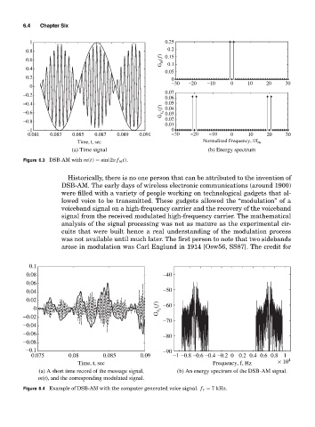
Figure 6.3 DSB-AM with m(t) = sin(2π f m t).
Historically, there is no one person that can be attributed to the invention of
DSB-AM. The early days of wireless electronic communications (around 1900)
were filled with a variety of people working on technological gadgets that al-
lowed voice to be transmitted. These gadgets allowed the “modulation” of a
voiceband signal on a high-frequency carrier and the recovery of the voiceband
signal from the received modulated high-frequency carrier. The mathematical
analysis of the signal processing was not as mature as the experimental cir-
cuits that were built hence a real understanding of the modulation process
was not available until much later. The first person to note that two sidebands
arose in modulation was Carl Englund in 1914 [Osw56, SS87]. The credit for
0.1
0.08 −40
0.06
0.04 −50
0.02
G x c (f)
0 −60
−0.02
−70
−0.04
−0.06
−80
−0.08
−0.1 −90
0.075 0.08 0.085 0.09 −1 −0.8 −0.6 −0.4 −0.2 0 0.2 0.4 0.6 0.8 1
Time, t, sec Frequency, f, Hz × 10 4
(a) A short time record of the message signal, (b) An energy spectrum of the DSB-AM signal.
m(t), and the corresponding modulated signal.
Figure 6.4 Example of DSB-AM with the computer generated voice signal. f c = 7 kHz.