
Page 186 - Fundamentals of Communications Systems
P. 186
6.8 Chapter Six
p ( [ p)]
m(t)exp j φ −φ
ˆ
m(t)exp jφ [ ] Re •[] ˆ m(t)
e
y t() • () 2 Im • []
z
m (t)sin 2φ [ e]
2
[
ˆ
exp − jφ p]
VCO LPF
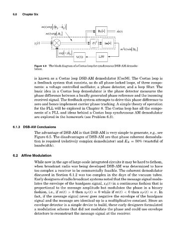
Figure 6.9 The block diagram of a Costas loop for synchronous DSB-AM demodu-
lation.
is known as a Costas loop DSB-AM demodulator [Cos56]. The Costas loop is
a feedback system that consists, as do all phase-locked loops, of three compo-
nents: a voltage controlled oscillator, a phase detector, and a loop filter. The
basic idea in a Costas loop demodulator is the phase detector measures the
phase difference between a locally generated phase reference and the incoming
received signal. The feedback system attempts to drive this phase difference to
zero and hence implement carrier phase tracking. A simple theory of operation
for the PLL will be explored in Chapter 8. The Costas loop has all the compo-
nents of a PLL and ideas behind a Costas loop synchronous AM demodulator
are explored in the homework (see Problem 6.3).
6.1.3 DSB-AM Conclusions
The advantage of DSB-AM is that DSB-AM is very simple to generate, e.g., see
Figure 6.5. The disadvantages of DSB-AM are that phase coherent demodula-
tion is required (relatively complex demodulator) and E B = 50% (wasteful of
bandwidth).
6.2 Affine Modulation
While now in the age of large-scale integrated circuits it may be hard to fathom,
when broadcast radio was being developed DSB-AM was determined to have
too complex a receiver to be commercially feasible. The coherent demodulator
discussed in Section 6.1.2 was too complex in the days of the vacuum tubes.
Early designers of radio broadcast systems noted that the message signal modu-
lates the envelope of the bandpass signal, x A(t) in a continuous fashion that is
proportional to the message amplitude but modulates the phase in a binary
fashion, i.e., if m(t) > 0 then x P (t) = 0 while if m(t) < 0 then x P (t) = π.In
fact, if the message signal never goes negative the envelope of the bandpass
signal and the message are identical up to a multiplicative constant. Since an
envelope detector is a simple device to build, these early designers formulated
a modulation scheme that did not modulate the phase and could use envelope
detectors to reconstruct the message signal at the receiver.