Page 188 - Fundamentals of Communications Systems
P. 188

6.10  Chapter Six

                        3
                                                                   x (t)     x z (t)
                                                                    c
                        2
                        1

                        0

                       −1
                       −2

                       −3
                          0              5              10             15             20
                                                       Time
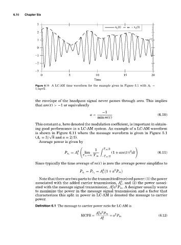
                       Figure 6.11 A LC-AM time waveform for the example given in Figure 5.1 with A c =
                       1/sqrt2.


                       the envelope of the bandpass signal never passes through zero. This implies
                       that am(t) > −1 or equivalently

                                                            −1
                                                     a <                                  (6.10)
                                                         min m(t)
                       This constant a, here denoted the modulation coefficient, is important in obtain-
                       ing good performance in a LC-AM system. An example of a LC-AM waveform
                       is shown in Figure 6.11 where the message waveform is given in Figure 5.1
                               √
                       (A c = 3/ 8 and a = 2/3).
                         Average power is given by
                                               #            T m /2            $
                                                        1                  2
                                              2
                                           = A    lim            (1 + am(t)) dt           (6.11)
                                              c
                                       P x c
                                                 T m →∞ T m  −T m /2
                       Since typically the time average of m(t) is zero the average power simplifies to
                                                            2     2
                                                            c
                                                P x c  = P r z  = A 1 + a P m
                         Note that there are two parts to the transmitted/received power: (1) the power
                                                                      2
                       associated with the added carrier transmission, A , and (2) the power associ-
                                                                      c
                                                                 2 2
                       ated with the message signal transmission, A a P m . A designer usually wants
                                                                 c
                       to maximize the power in the message signal transmission and a factor that
                       characterizes this split in power in LC-AM is denoted the message to carrier
                       power.
                       Definition 6.1 The message to carrier power ratio for LC-AM is
                                                          2 2
                                                        A a P m    2
                                                          c
                                                MCPR =          = a P m                   (6.12)
                                                           A 2
                                                            c
   183   184   185   186   187   188   189   190   191   192   193