
Page 191 - Fundamentals of Communications Systems
P. 191
Amplitude Modulation 6.13
mt() a ∑ A c
2 cos 2π f c t)
(
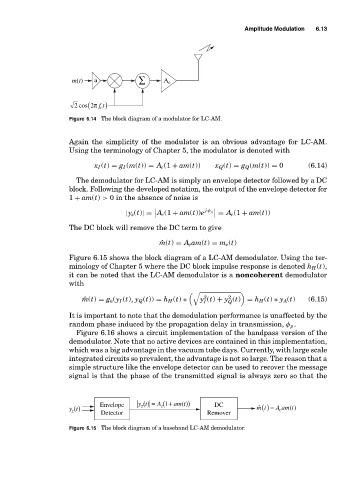
Figure 6.14 The block diagram of a modulator for LC-AM.
Again the simplicity of the modulator is an obvious advantage for LC-AM.
Using the terminology of Chapter 5, the modulator is denoted with
x I (t) = g I (m(t)) = A c (1 + am(t)) x Q (t) = g Q (m(t)) = 0 (6.14)
The demodulator for LC-AM is simply an envelope detector followed by a DC
block. Following the developed notation, the output of the envelope detector for
1 + am(t) > 0 in the absence of noise is
|y z (t)|= A c (1 + am(t))e j φ p = A c (1 + am(t))
The DC block will remove the DC term to give
ˆ m(t) = A c am(t) = m e (t)
Figure 6.15 shows the block diagram of a LC-AM demodulator. Using the ter-
minology of Chapter 5 where the DC block impulse response is denoted h H (t),
it can be noted that the LC-AM demodulator is a noncoherent demodulator
with
2
2
ˆ m(t) = g n (y I (t), y Q (t)) = h H (t) ∗ y (t) + y (t) = h H (t) ∗ y A(t) (6.15)
Q
I
It is important to note that the demodulation performance is unaffected by the
random phase induced by the propagation delay in transmission, φ p .
Figure 6.16 shows a circuit implementation of the bandpass version of the
demodulator. Note that no active devices are contained in this implementation,
which was a big advantage in the vacuum tube days. Currently, with large scale
integrated circuits so prevalent, the advantage is not so large. The reason that a
simple structure like the envelope detector can be used to recover the message
signal is that the phase of the transmitted signal is always zero so that the
(
DC
y t () Envelope yt () = A (1 + am t ) ) Remover ˆ mt () = A am(t)
c
z
c
z
Detector
Figure 6.15 The block diagram of a baseband LC-AM demodulator.