
Page 195 - Fundamentals of Communications Systems
P. 195
Amplitude Modulation 6.17
xt ()
I
mt()
+
2 cos 2π f t) Σ A c
(
c
−
π 2
xt ()
ht () Q
Q
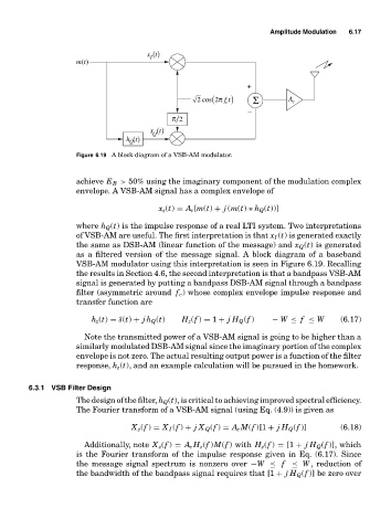
Figure 6.19 A block diagram of a VSB-AM modulator.
achieve E B > 50% using the imaginary component of the modulation complex
envelope. A VSB-AM signal has a complex envelope of
x z (t) = A c [m(t) + j (m(t) ∗ h Q (t))]
where h Q (t) is the impulse response of a real LTI system. Two interpretations
of VSB-AM are useful. The first interpretation is that x I (t) is generated exactly
the same as DSB-AM (linear function of the message) and x Q (t) is generated
as a filtered version of the message signal. A block diagram of a baseband
VSB-AM modulator using this interpretation is seen in Figure 6.19. Recalling
the results in Section 4.6, the second interpretation is that a bandpass VSB-AM
signal is generated by putting a bandpass DSB-AM signal through a bandpass
filter (asymmetric around f c ) whose complex envelope impulse response and
transfer function are
h z (t) = δ(t) + jh Q (t) H z (f ) = 1 + jH Q (f ) − W ≤ f ≤ W (6.17)
Note the transmitted power of a VSB-AM signal is going to be higher than a
similarly modulated DSB-AM signal since the imaginary portion of the complex
envelope is not zero. The actual resulting output power is a function of the filter
response, h z (t), and an example calculation will be pursued in the homework.
6.3.1 VSB Filter Design
The design of the filter, h Q (t), is critical to achieving improved spectral efficiency.
The Fourier transform of a VSB-AM signal (using Eq. (4.9)) is given as
X z (f ) = X I (f ) + jX Q (f ) = A c M(f )[1 + jH Q (f )] (6.18)
Additionally, note X z (f ) = A c H z (f )M(f ) with H z (f ) = [1 + jH Q (f )], which
is the Fourier transform of the impulse response given in Eq. (6.17). Since
the message signal spectrum is nonzero over −W ≤ f ≤ W, reduction of
the bandwidth of the bandpass signal requires that [1 + jH Q (f )] be zero over