
Page 200 - Fundamentals of Communications Systems
P. 200
6.22 Chapter Six
2 2
1.5
0
1
−2 0.5
|H Q (f)|, dB −4 arg{H Q (f)}, dB 0
−6 −0.5
−1
−8
−1.5
−10 −2
−3000 −2000 −1000 0 1000 2000 3000 −3000 −2000 −1000 0 1000 2000 3000
Frequency, f, Hz Frequency, f, Hz
(a) (b)
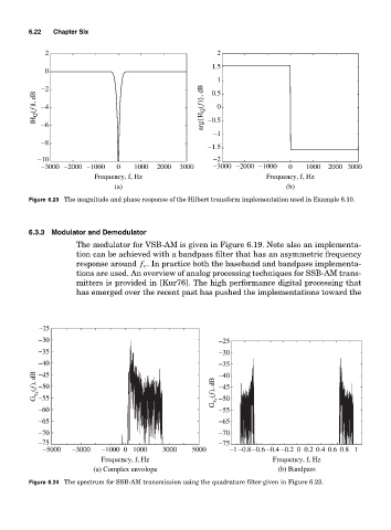
Figure 6.23 The magnitude and phase response of the Hilbert transform implementation used in Example 6.10.
6.3.3 Modulator and Demodulator
The modulator for VSB-AM is given in Figure 6.19. Note also an implementa-
tion can be achieved with a bandpass filter that has an asymmetric frequency
response around f c . In practice both the baseband and bandpass implementa-
tions are used. An overview of analog processing techniques for SSB-AM trans-
mitters is provided in [Kur76]. The high performance digital processing that
has emerged over the recent past has pushed the implementations toward the
−25
−30 −25
−35 −30
−40 −35
G x z (f), dB −50 G x c (f), dB −40
−45
−45
−55
−60 −50
−55
−65 −65
−70 −70
−75 −75
−5000 −3000 −1000 0 1000 3000 5000 −1 −0.8−0.6 −0.4 −0.2 0 0.2 0.4 0.6 0.8 1
Frequency, f, Hz Frequency, f, Hz
(a) Complex envolope (b) Bandpass
Figure 6.24 The spectrum for SSB-AM transmission using the quadrature filter given in Figure 6.23.