
Page 203 - Fundamentals of Communications Systems
P. 203
Amplitude Modulation 6.25
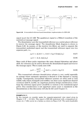
y (t) I/Q Down- y (t) y (t) y (t)
z
c
H
D
converter HPF Re[Σ] ˆ mt ()
f c
y (t)
L
LPF (•) −1
Figure 6.28 A transmitted reference based demodulator implementation for SSB-AM.
signal much like LC-AM. The quadrature signal is a Hilbert transform of the
notched-out message signal.
The demodulator uses the transmitted reference as a carrier phase reference
to recover the message signal. The demodulator block diagram is shown in
Figure 6.28. In essence, at the receiver two filters are used to separate the
transmitted modulated signal and the transmitted reference signal into two
separate path, i.e.,
y H (t) = A c [m(t) + j (m(t) ∗ h Q (t))] exp[ j φ p ] (6.27)
y L (t) = A c A r exp[ j φ p ] (6.28)
Since each of these paths experience the same channel distortion and phase
shift, the reference can be used to derotate the demodulated signal and recover
the message signal. This is easily seen with
y H (t) 1
y D (t) = = [m(t) + j (m(t) ∗ h Q (t))] (6.29)
y L (t) A r
This transmitted reference demodulation scheme is very useful especially
in systems where automatic operation is desired or if the channel is varying
rapidly. Consequently, transmitted reference systems are often used in land
mobile radio where multipath and mobility can often cause significant channel
variations [Jak74, Lee82]. An important practical design consideration is how
large the reference signal power should be in relation to the modulated signal
power. This consideration is not important unless noise is considered in the
demodulation so this discussion will also be left until Chapter 11.
EXAMPLE 6.11
In this example we consider again the computer-generated voice signal given in
Chapter 2 (W = 2.5 kHz). This signal is SSB-AM modulated with a transmitted ref-
erence at a 7 kHz carrier in a fashion as shown in Figure 6.27. The notch bandwidth