
Page 201 - Fundamentals of Communications Systems
P. 201
Amplitude Modulation 6.23
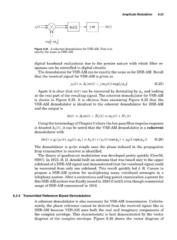
y t () Re[Σ] LPF ˆ mt ()
z
exp − [ jφ ] p
Figure 6.25 A coherent demodulator for VSB-AM. Note it is
exactly the same as DSB-AM.
digital baseband realizations due to the precise nature with which filter re-
sponses can be controlled in digital circuits.
The demodulator for VSB-AM can be exactly the same as for DSB-AM. Recall
that the received signal for VSB-AM is given as
y z (t) = A c (m(t) + jm h (t)) exp[ j φ p ] (6.25)
Again it is clear that m(t) can be recovered by derotating by φ p and looking
at the real part of the resulting signal. The coherent demodulator for VSB-AM
is shown in Figure 6.25. It is obvious from examining Figure 6.25 that the
VSB-AM demodulator is identical to the coherent demodulator for DSB-AM
and the output is
ˆ m(t) = A c m(t) + N I (t) = m e (t) + N I (t)
Using the terminology of Chapter 5 where the low pass filter impulse response
is denoted h L (t), it can be noted that the VSB-AM demodulator is a coherent
demodulator with
ˆ m(t) = g c (y I (t), y Q (t), φ p ) = h L (t) ∗ (y I (t) cos(φ p ) + y Q (t) sin(φ p )) (6.26)
The demodulator is quite simple once the phase induced in the propagation
from transmitter to receiver is identified.
The theory of quadrature modulation was developed pretty quickly [Osw56,
SS87]. In 1915, H. D. Arnold built an antenna that was tuned only to the upper
sideband of a DSB-AM signal and demonstrated that the voiceband signal could
be recovered from only one sideband. This result quickly led J. R. Carson to
propose a SSB-AM system for multiplexing many voiceband messages in a
telephony system. After a contentious and long patent examination a patent for
this SSB-AM system was finally issued in 1923 [Car23] even though commercial
usage of SSB-AM commenced in 1918.
6.3.4 Transmitted Reference Based Demodulation
A coherent demodulator is also necessary for VSB-AM transmission. Unfortu-
nately, the phase reference cannot be derived from the received signal like in
DSB-AM because VSB-AM uses both the real and imaginary components of
the complex envelope. This characteristic is best demonstrated by the vector
diagram of the complex envelope. Figure 6.26 shows the vector diagram of