Page 202 - Fundamentals of Communications Systems
P. 202

6.24  Chapter Six

                           0.8

                           0.6

                           0.4


                           0.2
                         x Q (t)  0


                          −0.2

                          −0.4

                          −0.6

                          −0.8
                             −1   −0.8  −0.6  −0.4  −0.2  0    0.2   0.4  0.6   0.8
                                                      x (t)
                                                       l
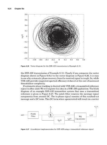
                       Figure 6.26 Vector diagram for the SSB-AM transmission in Example 6.10.


                       the SSB-AM transmission of Example 6.10. Clearly if one compares the vector
                       diagram shown in Figure 6.8(a) to the vector diagram in Figure 6.26, it is easy
                       to see why automatic phase recovery from the received signal is tough. So, while
                       VSB-AM provides improved spectral efficiency it does it at the cost of increased
                       demodulator complexity.
                         If automatic phase tracking is desired with VSB-AM, a transmitted reference
                       signal is often used. We will explore this idea in a SSB-AM application. The block
                       diagram of an example SSB-AM transmitter system that uses a transmitted
                       reference is given in Figure 6.27. The notch filter removes the message signal
                       components from around DC. The in-phase signal consists of this notched-out
                       message and a DC term. This DC term when upconverted will result in a carrier


                                                  A r


                                Notch                            x (t)
                                                                  I
                       m(t)                       Σ                                   x (t)
                                                                                       c
                                 Filter                                      I/Q
                                                                  x (t)  Upconverter
                                                                   Q
                                                         h (t)
                                                          Q
                                                                             f c
                       Figure 6.27 A modulator implementation for SSB-AM using a transmitted reference signal.
   197   198   199   200   201   202   203   204   205   206   207