
Page 183 - Fundamentals of Communications Systems
P. 183
Amplitude Modulation 6.5
mt () A c
2 cos(2πf t)
c
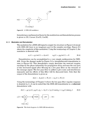
Figure 6.5 A DSB-AM modulator.
formulating a mathematical basis for the modulation and demodulation process
is given to J.R. Carson [Car22, Car26].
6.1.1 Modulator and Demodulator
The modulator for a DSB-AM signal is simply the structure in Figure 4.4 except
with DSB-AM there is no imaginary part to the complex envelope. Figure 6.5
shows the simplicity of this modulator. Using the terminology of Chapter 5, the
modulator is denoted with
x I (t) = g I (m(t)) = A c m(t) x Q (t) = g Q (m(t)) = 0 (6.4)
Demodulation can be accomplished in a very simple configuration for DSB-
AM. Given the channel model in Figure 5.8 a straightforward demodulator is
seen in Figure 6.6. This demodulator simply derotates the received complex
envelope by the phase induced by the propagation delay and uses the real part
of this derotated signal after filtering by a low pass filter as the estimate of
the message signal. The low pass filter is added to give noise and interference
immunity and the effects of this filter will be discussed later. Note that the
output of the demodulator is given as
ˆ m(t) = A c m(t) + N I (t) = m e (t) + N I (t)
Using the terminology of Chapter 5 where the low pass filter impulse response
is denoted h L (t), it can be noted that the DSB-AM demodulator is a coherent
demodulator with
ˆ m(t) = g c (y I (t), y Q (t), φ p ) = h L (t) ∗ (y I (t) cos(φ p ) + y Q (t) sin(φ p )) (6.5)
y t () Re • [] LPF m(t)
ˆ
z
exp − [ jφ ]
p
Figure 6.6 The block diagram of a DSB-AM demodulator.